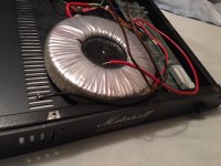
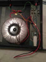
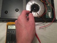
i,m wondering if the mains transformer for my 8008 valvestate rack amp is broken
measuring 30 volt between red and black wire
measuring 30 volt between red an brown wire
measuring 30 volts between black an brown wire
shouldn,t it be 59 volts between red and black
measuring 30 volt between red and black wire
measuring 30 volt between red an brown wire
measuring 30 volts between black an brown wire
shouldn,t it be 59 volts between red and black
Attachments


I don't think it says on that pdf but 59 volts sounds reasonable and would give DC rails of around -/+40v
Quick thought. Is your mains 115 or something and you have it wired for 230 volts.
Quick thought. Is your mains 115 or something and you have it wired for 230 volts.
the mains is 230 volts
i also measured on another 8008 that,s working fine and it measures 59 volts between red and black,
so i guess the transformer is broken then.
i bought it already broken ,rectifier was missing ,power transistors on channel a are also blown,
bought a new rectifier and power transistors but if the mains transformer has blown it,s no use to try if it works
It is very unusual for a transformer to be faulty. Your readings suggest something other than the transformer tbh. You have 30 volts on each winding. Are those 6.3A fuses OK?
-------------------------------------
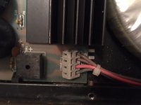
Try this by measuring directly on the transformer lead wires. Do not rely on any other leads or connectors in the amp. Disconnect the transformer completely so all the secondary wires are free.
So check these one at a time and with the mains disconnected.
1/ Confirm that Red to one of the Brown wires has continuity. It will read very low ohms.
2/ Confirm that there is no continuity between Red and the other Brown wire.
3/ Confirm that this other Brown wire has continuity to the Black wire. It should read the same ohms as step 1
----------------------------------------
4/ Now connect the Brown wires together and apply AC mains.
5/ Confirm the voltage between Brown and Red is 30 volts AC
6/ Confirm the voltage between Brown and Black is 30 volts AC
7/ Confirm the voltage between Black and Red is 60 volts AC.
-------------------------------------
Try this by measuring directly on the transformer lead wires. Do not rely on any other leads or connectors in the amp. Disconnect the transformer completely so all the secondary wires are free.
So check these one at a time and with the mains disconnected.
1/ Confirm that Red to one of the Brown wires has continuity. It will read very low ohms.
2/ Confirm that there is no continuity between Red and the other Brown wire.
3/ Confirm that this other Brown wire has continuity to the Black wire. It should read the same ohms as step 1
----------------------------------------
4/ Now connect the Brown wires together and apply AC mains.
5/ Confirm the voltage between Brown and Red is 30 volts AC
6/ Confirm the voltage between Brown and Black is 30 volts AC
7/ Confirm the voltage between Black and Red is 60 volts AC.
thanks very much!!
it,s working !!!
got 30 volts between red and brown and black and brown and 59 volts between red and black.
now i can continue rebuilding the amp ,bought new electrolytics replaced the blown output transistors,and before testing i,m going to build a light bulb limiter so i wont destroy all the new parts right away.
But before that i,ll check all resistors caps and other transistors,
again thanks very very much!!!!
You're welcome and good luck with the rebuild 🙂
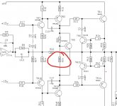
Remember the output transistors are Darlington types and also the amp seems to run with fixed bias. You might want to tweak this resistor when its working, increasing it will reduce the bias current.
For initial testing you can snip this resistor out and force a low bias condition.
Have fun.
Remember the output transistors are Darlington types and also the amp seems to run with fixed bias. You might want to tweak this resistor when its working, increasing it will reduce the bias current.
For initial testing you can snip this resistor out and force a low bias condition.
Have fun.