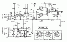
When using the tremolo channel the intensity control also changes the cathode resistance of the first gain stage between 820 and 1820 ohms. Why would they do that? It is kind of cool though because you can actually hear an audible difference with tremolo effect off. I believe it's got more grit with the intensity control to zero which would be cathode resistance of 820.
When using the tremolo channel the intensity control also changes the cathode resistance of the first gain stage between 820 and 1820 ohms.
Yes
Why would they do that?
Because it was simple, cheaper than buffering with another triode, and it worked
It is kind of cool though because you can actually hear an audible difference with tremolo effect off.
Multifunction then!
I believe it's got more grit with the intensity control to zero which would be cathode resistance of 820.
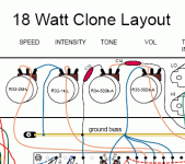
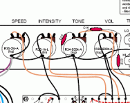
You sure? Check the two layout details attached. I think it might be the other way round. The cathode resistance is shared between the input stage and the phase shift oscillator.
Attachments
"You sure? Check the two layout details attached. I think it might be the other way round. The cathode resistance is shared between the input stage and the phase shift oscillator."
Yes the cathode is shared. Also you are correct, it was the other way around, more grit as the intensity is turned up.
And to clarify I am not knocking the design just making an observation of the genius of the amp.
Yes the cathode is shared. Also you are correct, it was the other way around, more grit as the intensity is turned up.
And to clarify I am not knocking the design just making an observation of the genius of the amp.
No worries, I didn't think you were knocking it! I was just absorbed in looking at the circuit, didn't mean to sound brusque.
My questioning was ambiguous, and possibly incorrectly leading. Yes, pot resistance does vary with intensity setting, thanks for clarifying that you hear more grit with higher intensity setting/resistance.
Without doing a proper analysis, it looks as if the higher cathode resistance and thus -ve Vgs on the signal triode is pushing the valve further towards cut off, increasing clipping on negative signal swings.
Both anode supplies run through a 100k resistor before the signal path triode supply branches off through a 220k. Having the intensity pot at maximum means that standing current in the oscillator triode is at a minimum. Anode voltage for the signal triode is thus maximum.
Going off on a slight tangent, this 100k/220k split supply arrangement has two effects with tremolo on. It increases the influence of the oscillator on the signal coming through, and reduces the oscillator signal on the anode of V3a, though there is a T-section CRC high pass filter immediately following, with values chosen to roll off below guitar bottom E.
Interesting. Thanks for prompting me to look at it.
Cool! I am glad you found this as interesting as I did. I noticed it on accident for I needed to get rid of some noise issues with the amp. The tremolo section was noisy with no signal (static noises) so I replaced both 100k and 220k and the noise is gone. Also I didn't like that the 100k resistors leads were not long enought to make it to the turrets on the board so someone added a piece of lead to make it. It wasn't a good mechanical connection more like the leads were glued together by solder. I also upped the wattage rating of the 100k to 1 watt.
- Status
- Not open for further replies.


