Hello
I'm currently working on two No. 436 with some issues.
Both work with 0V DC on the output... but i have DC on the XLR (both pins) port.
-0.9V on Amp #1 and -0.15V Amp #2
When hooking up a low impedance source #1 triggers DC Protection. When starting up with the source attached the servo amp immediatelly compensates that and the Amp works (no DC on the Outputs, full Outputpower).
#2 compensates the the 0.15V when attaching something without triggering the DC-protection
Checked the servo amplifier ... works ... when i trimm R1 i can see pin 6 of the Op amp moving from 0 to + 14 and -14V without getting DC on the output.
Moving R1 to extreme i see DC on the output as the servo OP Amp can no longer compensate. Works as expected.
I found a bad 2N5551 (hfe <10) in #1 and hope that replacing all four 2N5551 fixes the -0.9V problem.
In #2 all four 2N5551 seem O.K. (hfe at 150), but i will replace them anyways ... they were running way to hot for a long time ..... brown discoloration around them on the circuitboards
Any ideas what is causing the DC at the input ?
I've got the schematics, but there are no voltages listed at all ... :-(
What voltage drop should i see over CE of the 2N5551 ? in both Amps that voltage ist close to 100V ... wondering if something is wrong with the currentsources (Q20,Q23,Q24 and Q10,Q14,Q16,Q17). I expected a lower voltage on the 2N5551 and a larger voltage drop over the current sources.
The other thing that bothers me is that the documentation i have doesn't include a allignment procedure.
To what voltage must the two regulators be set. I currently have +/-104V on the LM317 / 337 outputs. Is that value correct for the 436 ?
Again, the manual doesn't tell any voltages (exept the -/-16V for the OP Amps 🙂).
Hope some one can help
Best regards
Peter
With 5mA and a Hfe of ca. 500, input current will be 10uA.
With a 49k9 input resistance, this will result in 0.5volt.
With a dual LM394 or Mat02 with a lower Hfe, you will get a higher input voltage.
Replacing the 2N5551 won't change to the input offset, the are used as cascodes to the input dual.
Trim R1 to get 0Volt on the output of the servo when the amp is stable after 30 minutes.
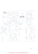
In the attached schematic you can see all voltages.
Hans
With a 49k9 input resistance, this will result in 0.5volt.
With a dual LM394 or Mat02 with a lower Hfe, you will get a higher input voltage.
Replacing the 2N5551 won't change to the input offset, the are used as cascodes to the input dual.
Trim R1 to get 0Volt on the output of the servo when the amp is stable after 30 minutes.
In the attached schematic you can see all voltages.
Hans
Attachments
Hi Hans,
thanks for your extremly fast reply 🙂
i will check .... in the troubled Amp the LM394 was replaced by two thermically coupled transistors (BC550B ... looks like a bad choice .. shouldn't it be a "C" type).
Will try to get an LM394 to make both amps identical ...
Thanks again
Peter
thanks for your extremly fast reply 🙂
i will check .... in the troubled Amp the LM394 was replaced by two thermically coupled transistors (BC550B ... looks like a bad choice .. shouldn't it be a "C" type).
Will try to get an LM394 to make both amps identical ...
Thanks again
Peter
#1 is done ... indeed now i have -0.45V on both input Pins. 0V on Pin 6 of the Servo Amp and +/-113V as Operating Voltage.
Will take care of #2 next week ..... hope to get the same results ... 🙂
Thanks
Will take care of #2 next week ..... hope to get the same results ... 🙂
Thanks
