Well I like a lot of people have heard tales of the MARANTZ T1 amplifier.
It had four 845's and four 300B's. It should be noted that two of the 845's were for plate voltage rectification.
It had an all UTC transformer line up.
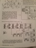
I've always wondered what the inspiration for the T1 was? And one day while reading some old issues of Sound Practices I noticed an article where Joe Roberts had a schematic from a 1936 UTC catalog with a circuit almost dead on the T1.
I included both schematics so you could compare yourself.
At some point I decided to take on the challenge of building this god damn thing. But felt like there were some things that could be changed and I also knew there were some things that would have to be changed based on the build itself.
After a decent, or at least what I thought was a decent chassis was attained, I started filling it with all the lower compartment Chokes, transformers and capacitors.
The top of the chassis would hold the following UTC LS-91 Choke, LS-12, LS-22, LS-56, interstage transformers and the Freed QGA-42 100 watt output transformer. Two HV capacitors
I chose a Freed QGA-42 over the UTC LS6L4 because it's rated for the full 100 watts an 845 can develop.
Also the T1 had a large DC power supply for the filaments, I did not have room for this so all my filaments are AC. Also my plate supply for the 300B was only good for one pair. So I went with a 6SN7 after the LS-12 to power the LS-22 then 300B to drive the 845 outputs.
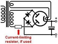
I included Bias meters for the 300B's & 845's. The HV Hybrid rectifier can use 3B22, 866A, or 836 rectifiers. But it delivers full bridge rectification via a variac that allows me to raise the voltage slowly to 1KV.
The output of the variac goes through an Edison 6.3 volt time delay.
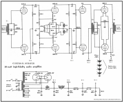
Input to the LS-12 goes through a Daven attenuator. I included two other schematics from the Golden Ear & Curtiss R Schafer amplifiers.
I borrowed from both these circuits. These circuits and more can be found on Kurt Lilenthals website 100 amps to tip your hat too: https://bit.ly/3ecFuc8
First impressions are really good. I've been playing some Deadmau5 through the amp, lots of Bass I'm just sad that it took me 3 years to marshal all the iron to build just one monoblock. But the damn thing works.
And at the end of the day is there anything better than listening to audio through something you built?
I think not!!!
It had four 845's and four 300B's. It should be noted that two of the 845's were for plate voltage rectification.
It had an all UTC transformer line up.
I've always wondered what the inspiration for the T1 was? And one day while reading some old issues of Sound Practices I noticed an article where Joe Roberts had a schematic from a 1936 UTC catalog with a circuit almost dead on the T1.
I included both schematics so you could compare yourself.
At some point I decided to take on the challenge of building this god damn thing. But felt like there were some things that could be changed and I also knew there were some things that would have to be changed based on the build itself.
After a decent, or at least what I thought was a decent chassis was attained, I started filling it with all the lower compartment Chokes, transformers and capacitors.
The top of the chassis would hold the following UTC LS-91 Choke, LS-12, LS-22, LS-56, interstage transformers and the Freed QGA-42 100 watt output transformer. Two HV capacitors
I chose a Freed QGA-42 over the UTC LS6L4 because it's rated for the full 100 watts an 845 can develop.
Also the T1 had a large DC power supply for the filaments, I did not have room for this so all my filaments are AC. Also my plate supply for the 300B was only good for one pair. So I went with a 6SN7 after the LS-12 to power the LS-22 then 300B to drive the 845 outputs.
I included Bias meters for the 300B's & 845's. The HV Hybrid rectifier can use 3B22, 866A, or 836 rectifiers. But it delivers full bridge rectification via a variac that allows me to raise the voltage slowly to 1KV.
The output of the variac goes through an Edison 6.3 volt time delay.
Input to the LS-12 goes through a Daven attenuator. I included two other schematics from the Golden Ear & Curtiss R Schafer amplifiers.
I borrowed from both these circuits. These circuits and more can be found on Kurt Lilenthals website 100 amps to tip your hat too: https://bit.ly/3ecFuc8
First impressions are really good. I've been playing some Deadmau5 through the amp, lots of Bass I'm just sad that it took me 3 years to marshal all the iron to build just one monoblock. But the damn thing works.
And at the end of the day is there anything better than listening to audio through something you built?
I think not!!!
Attachments
-
![20211220_152555[1].jpg](/community/data/attachments/914/914947-a389a3afc8339d198b4a6617f05576a4.jpg?hash=o4mjr8gznR) 20211220_152555[1].jpg355.2 KB · Views: 231
20211220_152555[1].jpg355.2 KB · Views: 231 -
![20211220_152844[1].jpg](/community/data/attachments/914/914948-9a70ed83d0a8255b949275d08271a461.jpg?hash=mnDtg9CoJV) 20211220_152844[1].jpg334.6 KB · Views: 193
20211220_152844[1].jpg334.6 KB · Views: 193 -
![20211220_152908[1].jpg](/community/data/attachments/914/914949-fc3af7fb5733eb08b7f654d5310bdfb8.jpg?hash=_Dr3-1cz6w) 20211220_152908[1].jpg360.8 KB · Views: 188
20211220_152908[1].jpg360.8 KB · Views: 188 -
![20211220_153046[1].jpg](/community/data/attachments/914/914950-145ca04d0e360b22aa37d17842707217.jpg?hash=FFygTQ42Cy) 20211220_153046[1].jpg377.2 KB · Views: 208
20211220_153046[1].jpg377.2 KB · Views: 208 -
![20211220_152818[1].jpg](/community/data/attachments/914/914951-d279ed8bcd2b49d27cb3367a3546b88a.jpg?hash=0nnti80rSd) 20211220_152818[1].jpg356.4 KB · Views: 208
20211220_152818[1].jpg356.4 KB · Views: 208 -
 dc208427835fb1801da1c8f340b82456.jpg131.8 KB · Views: 231
 -
 761c4547a060c03e1a7c3815787d7caf.gif30.3 KB · Views: 248
 -
 Curtiss-R.Schafer-30W-high-fidelity-audio-amp-300A-PP-1947-ed.png772 KB · Views: 222
 -
 Golden-Ear-6B4G-PP-iron-triode-1950-ed.png736.5 KB · Views: 265
 -
![20200910_161741[1].jpg](/community/data/attachments/914/914970-56ecfee56053a9d5ba849d9ee548cd94.jpg?hash=Vuz-5WBTqd) 20200910_161741[1].jpg428.8 KB · Views: 220
20200910_161741[1].jpg428.8 KB · Views: 220 -
 bridge3.jpg14.7 KB · Views: 199