I have a SR6010 going into protection mode when powered up.
Red power led blinking in .5 sec intervals.
I managed to check the protection status in service mode before it shuts down.
Its an ASO protection as expected.
No shorts in speaker cables as it goes into protection with and without speakers attached.
It has been running hot in a low shelf so I suspect output transistors. Only RL front channels outputs have ever been used.
I managed to tear it apart and desoldered both front channel transistor pairs and the center channel too to have a reference.
All 2sd and all 2sb tested the same using ohms on my multimeter.
So they seems ok, or...
How do I proceed from here?
Thx 😊
I believe this is an 'AV Receiver' and as such will have some complex circuitry...
We need a service manual to advice in detail.
Generic testing rules apply, if it actually shuts down you may need to find a way to override that so it can be worked on 'live' to see what is going on. Most protection issues are down to failed output stages causing high DC offset and/or a high current situation. If its a normal Class AB stage you might be able to 'busk it' without a manual. For us to have any clue we need to see the circuit details.
Hi mooly, thx for responding. Of course. Here it is.
Yes its one of their older avr's. I had it for about 10 years from new.
There is a protection override option in service mode but I was afraid to use it, risking more damage.
This means though I have to assemble it all. Its really tough to reach anything inside without disassembling. Its so cramped 😊
I only have a multimeter as testing equipment. I also have an LCR T4 clone, its reading the darlington transistors as thyristors...
Edit. The service manual is too big to upload. Heres a link instead.
https://www.google.com/url?sa=t&sou...MQFnoECCwQAQ&usg=AOvVaw0RpsH_w_i-V6C3MwhwYFqM
Well... it's horrendously complicated as I expected.
The best you can do is try and see what actually happens in the time before it goes into protect. There seem to be seven power amplifier channels each with DC offset, overcurrent and temperature individually monitored and the info fed into a uP.
See what happens to the rails to all these amps and whether they come up or not. If they come up and stay up you can work on it. If they only come up for a few seconds then its more difficult as you have to keep powering it on and off. Begin by looking at the DC offset and over current for each amp and also the temperature monitoring. See if one channel is different to the others.
There look to be points where a lot of this data can be measured. All you can do is see what you find. You might get lucky.
In the few seconds from power up till protection mode I manage to enter protection status. It says ASO which aligns with the 0.5 sec blinking. Thats a fault in the power amp; shorted speaker cable or impedance mismatch. The speakers are nominel 6 ohms and I am certain the speaker terminals have never been shorted.
Will I do harm assembling the amplifier without the RL front channel output transistors?
If not this will confirm its a fault in one of these circuits if the amp powers up.
I will test the rails this thursday and be back. I guess I will be looking for voltage between rail and ground.
Will I do harm assembling the amplifier without the RL front channel output transistors?
If not this will confirm its a fault in one of these circuits if the amp powers up.
I will test the rails this thursday and be back. I guess I will be looking for voltage between rail and ground.
If you remove the output transistors from any channel then the output node effectively floats. Whether it would assume some voltage in that state is a bit of an unknown so if you do pull the transistors then I think you would have to also tie the output of that channel to ground and also pull these diodes (one from each side). The feedback loop will now be broken and so the voltages in the driver stage will swing to a rail but that shouldn't be an issue as a short term test.
Obviously doing all that is a bit of an unknown and so at your own risk.... or rather the amps risk 🙂

Obviously doing all that is a bit of an unknown and so at your own risk.... or rather the amps risk 🙂
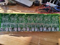
I would just measure all outputs in circuit, pretty easy since they are in a long row. The most common is a short so just do a quick check on all of them. If you find shorted outputs double check emitter resistors and other components on the broken channel.This youtube video is not that bad.
First - unhook each channel's power, there should be individual power going to each power section of the PCB.
This will tell you specifically whcih channel is the culprit.
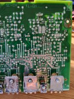
Gong by memory, but easy to find on the back of the PCB - you need to replace (2-3) SMD BJTs, 2n5401 and/or 2n5501 (MMBT5551 and MMBT5401). These go out of spec from heat and fool the ASO into thinking there is an issue when there isn't. However, I have done this repair twice and on one of the repairs when I turned it on, a different channel Darlingtons blew - unsure if it was related, or bad already and the protection picked up the ASO fault before the DC fault - so you are warned.
You have two options for repair
1) you can remove the entire board and all transistors from the heatsink, flip it over and repair the SMDs
2) you can carefully bend the board with the transistors still attached to the heatsink just enough to have room to replace the SMDs
Either way - be very careful or you will damage the pads on the Darlington(s), or break off a leg and will have another repair for yourself.
This will tell you specifically whcih channel is the culprit.
Gong by memory, but easy to find on the back of the PCB - you need to replace (2-3) SMD BJTs, 2n5401 and/or 2n5501 (MMBT5551 and MMBT5401). These go out of spec from heat and fool the ASO into thinking there is an issue when there isn't. However, I have done this repair twice and on one of the repairs when I turned it on, a different channel Darlingtons blew - unsure if it was related, or bad already and the protection picked up the ASO fault before the DC fault - so you are warned.
You have two options for repair
1) you can remove the entire board and all transistors from the heatsink, flip it over and repair the SMDs
2) you can carefully bend the board with the transistors still attached to the heatsink just enough to have room to replace the SMDs
Either way - be very careful or you will damage the pads on the Darlington(s), or break off a leg and will have another repair for yourself.

from the internet - very basic overview of the protection achematic in a Denon, but similar to a Marantz.

Thanks for all the responses, I really appreciate it.
Its been too long time since I touched this project, sometimes life prioritise different.
@bullittstang thx for the brilliant idea of unhooking power one by one. It narrowed it down to front left channel.
The transistors q7425, q7431 and q7433 in circuit on both front channels measured within 5% indicating no faults on front left power transistors.
Looking at the PCB I see no sign of high temperatures on neither sides.
I found q7138 and q7139, visually they look fine but still can be faulty as you say.
I will try to find a supplier within EU selling these. Its worth replacing them first.
Attachments
Looking at schematic diagrams 33/38 it seems ASO is detected by q7139/bt5551 solely. Q7138/bt5401 does thermal detection.
I guess it's ok to substitute bt5551 to 2n5551. MUCH easier to work with 😄
I guess it's ok to substitute bt5551 to 2n5551. MUCH easier to work with 😄
You can sub, but make sure of pin out and clearance on heatsink. Could heat it up and cause false tripping.
True. A 2n5551 will sit in hot air flow while smd 5551 will benefit from the small, but present, cooling factor from the pcb.
Could wire it and locate it on the opposite side of the pcb.
Could wire it and locate it on the opposite side of the pcb.
The 2n5xxx tops at 150⁰C though. I hope the pcb never get that hot 😮
Both transistors are ordered and all I can do is sit back and wait.
Unless theres something else I can do in the meantime?
Both transistors are ordered and all I can do is sit back and wait.
Unless theres something else I can do in the meantime?
Update.
Today I finally recieved the 2n5551 and 2n5401.
I was aware of the different pin out when replacing bt5551 with 2n5551. Soldering went fine.
But still tripping.
I unhooked FL power connector as before and it stayed ON, relays clicking and all - for about 2 seconds after last relay then I had pops and smoke from R7329, 7330, 7629 and 7630. Base resistors for both darlingtons on C and SBL channels 😒
- Home
- Amplifiers
- Solid State
- Marantz SR6010 in protection mode