Hi everyone and merry christmas 🙂
I am currently trying to repair an old Marantz PM-80mkII.
The schematics are in attachment.
The thing outputs around 150mV DC at the right channel. The other one is fine (~1.5 mV DC). It is more or less the same in AB class and in A class.
As far as I can tell, nothing is obviously dead inside. I switched almost all transistors between channels (except Q704, Q706 and Q708), the issue is still at the right channel.
However, when measuring DC bias points as indicated in the schematics, I have 0V DC everywhere after Q716/Q718 (no input, no load).
The other channel is completely fine, and all DC measurements are correct.
Trouble is, I still cannot find any dead component...
Any ideas?
Attachments
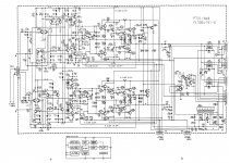
Check voltages around and voltage drop across R742 and R744. Looks like there may be no current flowing there for some reason. Are the LEDs operating? What about Q712/714?
Your fault may be as basic as a bad solder joint or trace.
Your fault may be as basic as a bad solder joint or trace.
Last edited:
You were 100% right, the fault was due to bad solder joints.
Although I checked many times, I did not see the broken solder joints on Q716 and Q718 until I tried to move them.
Now, I have around 5mV DC at the output, which is perfectly OK.
Only thing left is to adjust the bias currents and I will be able to enjoy this nice amp.
Thank you very much for your help! 🙂
Hi,
Q701 and Q702 are the most likely cause. ( Differential pair ).
Any variation in these transistors can cause voltage offset problems.
While amplifier is on touch the transistors with a plastic pen. Moving them will sometimes
cause changes. Do this with the voltage being monitored. De-solder them and look for a green color between the pins. If there is color, they are are definitely faulty.