hello,
my Marantz PM 7200 has distortion at all volumes on the left channel ( right is ok)
The left heatsink stays cold during operation (right one gets warm as expected)
I swapped over the speakers to confirm its the amp. All inputs have the same distortion.
I have limited knowledge and have tested the transistors on the heatsinks which all seem ok ( I tested them in circuit though, does this give correct measurements on the multimeter?). Everything else looks ok (nothing fried!)
Any advice would be appreciated to get it working properly. Please give detailed testing procedures if poss.Thanks
hello again!
There has been a development- I now have no output. The initial click happens when it is switched on but no relay click for the speakers. If left on it sometimes eventually clicks on and pressing the speaker 1 button (where the speakers are connected to) you get a pop and the woofer pushes out (i dont want to do it again incase it damages speakers!).
There has been a development- I now have no output. The initial click happens when it is switched on but no relay click for the speakers. If left on it sometimes eventually clicks on and pressing the speaker 1 button (where the speakers are connected to) you get a pop and the woofer pushes out (i dont want to do it again incase it damages speakers!).
Somewhere around ten to twenty years the electrolytic capacitors in electronic gear leak out the water and lose capacity. The cheap ones used on consumer gear are sealed with rubber that is attacked by oxygen, operating or sitting still. The good news is, amplifiers don't have very many and it can be economic to replace the caps if you do it yourself. I just change them all, without measuring; I understand others believe in taking them all out and measuring them once a month. Like a twenty year old tire, just because it holds air today doesn't mean it will hold air tomorrow.
These are aluminum cans with plastic wrap with a bunch of minus's in balls pointing at one lead, or small peanut M&M's with a plus on one lead. Usually they are marked 1 mf or higher. New marking at the distributors turns 1 mf into 1 uf, as if a Uniform was a deformed Micro. You look them up at distributors by clicking passive components, then capacitors, then aluminum electrolytic. I like to buy the 2000 hour up expected life ones, as I have recapped my dynakit equipment 3 times and that is too often if they sell longer life caps now. The peanut ones are tantalum:80% of the tantalums I have owned or bought have been defective, so I replace tantalums with aluminum plus a 0.1 mf ceramic cap wired parallel. Time marches on, and frequently in 1-10 mf caps you can replace them with film dielectric caps, if you can make it fit. Some electrolytics are marked "NP" for non-polar. The small ones I make it a point to replace with film.
WIth your channel going dead, probably an electrolytic cap has activated the protection circuit (good) or shorted out a rectifier or resistor in the power circuit (requires further debug). Check your components before the first big cap after the transformer to save yourself an additional shipping charge.
Remove all jewelry so you don't burn your fingers off. Caps can hold charge after the power is off, and over 25V can kill you if it crosses your heart, so read aikenamps.com tech info technician safety button about proper rules for people repairing amps.
Last edited:
marantz pm 7200
Thanks for the answer.
Being a novice, I'm a little lost!
There are capacitors all over the circuit boards. Where should I start?
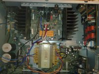
There are 2 large ones on the power up board. Both look the same with: "85 degrees c V1200 u f (m) Marantz blank" written on them. Do you think these may be the culprits?
There are about 6 small ones on each output channel circuit- do i need to check all of these?
None of them appear to be leaking or bulging at the top.
I am a little confused by the 0's and m+m's as I cant see any markings like that on any of them
I'll try to attatch a photo of the amp.
Thanks again for your help!
Thanks for the answer.
Being a novice, I'm a little lost!
There are capacitors all over the circuit boards. Where should I start?
There are 2 large ones on the power up board. Both look the same with: "85 degrees c V1200 u f (m) Marantz blank" written on them. Do you think these may be the culprits?
There are about 6 small ones on each output channel circuit- do i need to check all of these?
None of them appear to be leaking or bulging at the top.
I am a little confused by the 0's and m+m's as I cant see any markings like that on any of them
I'll try to attatch a photo of the amp.
Thanks again for your help!
Attachments
Given your level of experience, you'd best hand the amp over to an experienced tech. Most probably there's a defective transistor in the first stages of the left power amp.
You can check all the remaining transistors with the diode test if you want. Also look at the big white resistors, they're the emitter resistors and can cause symptoms like yours if way out of spec.
You can check all the remaining transistors with the diode test if you want. Also look at the big white resistors, they're the emitter resistors and can cause symptoms like yours if way out of spec.
Checking capacitors takes a $150 meter. I just look at the calender and change the ones over twenty years old.
You can check Output Transisors with a double diode test on a cheap DVM. But you have to take them out of circuit. OT's go because you shorted the output somehow, usually. More common in band amps than home amps with a fixed setup. You have to remove the O't's to check them. Your small signal transistors, new people are likely to damage them removing them and replacing them for test. Learn to solder on the caps.
I don't see any tantalum caps in your picture.
Change 2 at a time if you decide to do that, then do a sound check to see if you made it better.
Your 1200 uf caps are more likely to trip the breaker or short out the rectifier than sound bad. but if it is over twenty years do them too.
I did all the big caps in my late Dad's 197? FM radio last year, but didn't have any 1,2's or 3's when I did it. it is down to 63 deg F in here for the first time this winter today, and it sounds like **** and has no sensitivity. Time to do the rest of them. Did this fuzzy noise start when the room temperature dropped for winter? More likely e-caps. I've never lost a small signal transistor that wasn't cooked by a shorted O.T.
Paying a professional repairman is not diy "do it yourself'. But read aikenamps.com tech button technician safety button before touching metal inside. 50 VDC can burn your finger off if you wear jewelry, or stop your heart if you use both hands at once and make a mistake.
Last edited:
I changed all the caps on the output circuit (with the heat sinks). The speaker relays click into life after 10 seconds or so of switching on, and pressing "speaker 1" (or "speaker 2") buttons.
I thought this is it fixed, but when i connect the speakers, there is only very slight sound in the right speaker and nothing in the left (same through headphones).
The heat sinks stay cold. I tested the rectifier (out of circuit) before the big caps on the power circuit, and have tested all of the transistors (not all out of circuit though) and they seem ok.
Do you think I need to replace every cap in the amp, or look at something else? I dont feel like giving up, its become a challenge!
Thanks for any help.
Film dielectric capacitors and ceramic disks have very long life and are not usual suspects.You might have a corroded switch or volume control or tone, or a bad pin connector or solder joint. I think you need to get a DVM or better a simpson 260 VOM or VTVM, and check the dc voltages of the good channel against the bad channel. That will help you find simple problems. Then if those are okay, Use the 2 VAC scale of the VOM to check the signal as it goes in and goes through. An oscilloscope is even better, I have a B&K 2120 now with 20 Mhz response, very obsolete. I have found modern DVM's to be insensitive to low AC voltage at music frequencies, giving zero results or stupid results like 26 VAC on dead circuits. You can also make a sound probe out of a powered computer speaker with .1 uf 600 v capacitors between the test leads and the tip and ring of the input connector. Use a transistor radio or something as a sound source out the earphone jack. Cheesy ones are $1, but I protect my radio with an in-series .1 capacitor also since DC might leak out the input jack of a defective amp. Use the speaker return as the probe ground generally.
You might be able to find a schematic diagram on eserviceinfo.com or someplace. But the schematics are all pretty similar, just look on some of the units on here for typical commercial circuits. Radios are tricky without a schematic, but I fixed my first transistor amp without one, and with so many of the parts burned up I had to guess whether they were PNP or NPN. I guessed some things wrong, the amp worked okay at 20 watts for years before I found diyaudio and got the parts to make it put out 120 watts. About not giving up, I'm listening to that amp today. I've made some improvements on it to make it sound better at low volume and cold room temperatures, and I've revised the cooling to eliminate some design faults. Your Marantz may be better designed, but if you have a decent heat sink and a working transformer with between +-24 to +-70 VCT, you have enough to repair or build an amp.
You might be able to find a schematic diagram on eserviceinfo.com or someplace. But the schematics are all pretty similar, just look on some of the units on here for typical commercial circuits. Radios are tricky without a schematic, but I fixed my first transistor amp without one, and with so many of the parts burned up I had to guess whether they were PNP or NPN. I guessed some things wrong, the amp worked okay at 20 watts for years before I found diyaudio and got the parts to make it put out 120 watts. About not giving up, I'm listening to that amp today. I've made some improvements on it to make it sound better at low volume and cold room temperatures, and I've revised the cooling to eliminate some design faults. Your Marantz may be better designed, but if you have a decent heat sink and a working transformer with between +-24 to +-70 VCT, you have enough to repair or build an amp.
Last edited:
hello again!
There has been a development- I now have no output. The initial click happens when it is switched on but no relay click for the speakers. If left on it sometimes eventually clicks on and pressing the speaker 1 button (where the speakers are connected to) you get a pop and the woofer pushes out (i dont want to do it again incase it damages speakers!).
If the woofer pushes out and stays out, it's highly likely that there's DC on the output of the faulty channel. The speaker protection circuit should kick in and open the speaker relays to prevent damage, because indeed DC would damage your speakers.
It's been suggested that bad caps would be the cause of this. I find that unlikely, a PM7200 isn't that old and one of the channels was working without distortion. That fact alone told me that at least the two big ones are OK, because left and right channel share the positive and negative PSU that these big boys buffer.
Don't change components haphazardly, trace the problem first. The beauty of a stereo amp is that you have (or should I say had?) a working channel to campare the faulty one against.
If you have no clue what you're doing, please find someone who can help you. There are potentially lethal voltages present in amps.
First of all, before proceeding any further, I highly recommend that you find a service manual for your specific amp. Unless you are a professional who has familiarity with failures on specific brands/models and does this everyday, the manual and schematics are essential. Second, I think you need to determine if you simply want this amp fixed, or if you want to learn how to fix electronics. I say that because this may take you a LONG time to figure out and cost quite a bit in part swapping if you are unfamiliar with troubleshooting electronics. If you are only interested in getting the amp fixed, it might be cheaper and will definitely be faster to turn it over to a pro. If you are interested in learning how to fix electronics, I would suggest the first thing to learn is how to test the various components and acquire the necessary equipment. There is lots of info out there for the beginner. I started with the following site: testingelectroniccomponents.com, which costs a little money but I did learn a lot. You will also want to find information around how each component behaves in a circuit. I think you will need to prepare yourself for the investment in time and money that this adventure will take you on! I started the same way and it has taken years to become semi efficient at troubleshooting.
In the USA, the only pro one needs for consumer electronics repair is the garbage man. My brother can't even get his ford trucks fixed in Houston, he says it is more fun taking hundred dollar bills and setting fire to them. I had a TV repaired by a pro in 1988 when I was working too much. It lasted almost a year.If you are only interested in getting the amp fixed, it might be cheaper and will definitely be faster to turn it over to a pro.
Even if you pay the pro to totally replace the expired electrolytic caps, the chances of him using any parts that will last more than 1000 hours is zero. That is why the distributors stock all the short life parts so deeply.
Last edited:
I know this is an old thread but having a PM7200 on the bench recently, I was looking around to see what are the common faults. Didn't come up with much so I took a look at it myself. The complaint was that the amp had no sound and true enough, turning the power on didn't make any relays click.
I discovered that even though the amp is about 6-7 years old now, the electrolytic caps around the power amp board have all fallen below spec. The ones that supply voltage for the relays to open were reading very low and changing them got the relays working again. However I believe the amp will need a full recap job as every cap I checked was well below spec.
This amplifier runs hot during normal operation and I suspect this is what causes the caps to fail. Even though most of them are rated at 105'C, after 5 years of operation, even these caps start to fail. Oh and just like this topic starter's amp, when the relays on the one I was working on refused to open, one channel's heatsink did get very hot and one remained cold. This led me to believe the transistors had failed but alas this was not the case. Once the relays clicked open, the amp behaved normally and both heatsinks were pretty much the same temperature.
- Status
- Not open for further replies.
- Home
- Amplifiers
- Solid State
- marantz pm 7200 left channel distortion