After unboxing, removing their tops, and blowing some stink off, I got them warming quickly and actually played music! Here they are holding the amppads to the floor.

Removed a bottom cover and was please to see much room around the output-stage PS caps, so I filled a little of it on two amps with pairs of BlackGate VK-series 2200/35 bypass caps. (Original caps are ELNA for Audio 22000/50s.)

Will concentrate, initially, on the inputs, replacing the RCAs with Furutechs, adding 50K TDK pots*, and, to the lower-frequency amps, adding SoniCap Platinum hi-pass filter caps for the Vandersteen 5As' bottom ends**.
Will post schematic soon.
* Will lift the original 56K load resistor too. The amps have WAY too much--as in almost 30dB--Voltage gain, so the pots will allow me to get my preamp gain control where I want it, reduce system noise slightly, and tweak the level of the high frequencies easily.
** The VS Quatros, 5s, and 7s require a preceding, inline, or built-in-the-amp high-pass filter since the speaker has none in its x-overs.
Removed a bottom cover and was please to see much room around the output-stage PS caps, so I filled a little of it on two amps with pairs of BlackGate VK-series 2200/35 bypass caps. (Original caps are ELNA for Audio 22000/50s.)
Will concentrate, initially, on the inputs, replacing the RCAs with Furutechs, adding 50K TDK pots*, and, to the lower-frequency amps, adding SoniCap Platinum hi-pass filter caps for the Vandersteen 5As' bottom ends**.
Will post schematic soon.
* Will lift the original 56K load resistor too. The amps have WAY too much--as in almost 30dB--Voltage gain, so the pots will allow me to get my preamp gain control where I want it, reduce system noise slightly, and tweak the level of the high frequencies easily.
** The VS Quatros, 5s, and 7s require a preceding, inline, or built-in-the-amp high-pass filter since the speaker has none in its x-overs.
Last edited:
And since the originals are 50V caps, did you check that the actual voltage on these is LESS THAN the 35V rating of the black gates????
Nico, the black box in the center is a Vandersteen VCC-1 centerchannel-dialog speaker*. I've improved that, too, and haven't finished the cosmetics; that's why the black cloth is drooping.
Ilimzn, yes indeed I did. Voltage on schematic is 31; actual at my house is about 32.
BTW the amp has a completely separate (starting with PT secondaries) supply for the frontend--51Volts. I will NOT be putting 50V caps in that. 🙂
Have found another spot where output-stage PS bypass caps sort of fall in and have added a couple more BGs per amp, this time 100/50 K-series.
* Mine is a combination multichannel-music/home-theater system. The 8-feet-wide (NOT diagonal) screen is suspended on chains, and it's hung up, out of the way for these pics. The screen fills all but about 3" per side of the space between the V-steen 5As.
Ilimzn, yes indeed I did. Voltage on schematic is 31; actual at my house is about 32.
BTW the amp has a completely separate (starting with PT secondaries) supply for the frontend--51Volts. I will NOT be putting 50V caps in that. 🙂
Have found another spot where output-stage PS bypass caps sort of fall in and have added a couple more BGs per amp, this time 100/50 K-series.
An externally hosted image should be here but it was not working when we last tested it.
* Mine is a combination multichannel-music/home-theater system. The 8-feet-wide (NOT diagonal) screen is suspended on chains, and it's hung up, out of the way for these pics. The screen fills all but about 3" per side of the space between the V-steen 5As.
Last edited:
Nice setup.
I can't help thinking that keeping small children away from it would present a challenge, though. A friend of mine had his precious Linn Asaka cartridge ruined when his 2-year old son decided to investigate it. 😉
I can't help thinking that keeping small children away from it would present a challenge, though. A friend of mine had his precious Linn Asaka cartridge ruined when his 2-year old son decided to investigate it. 😉
Jeff, is retired - small kids are in the distant past. Nobody will leave kit on the floor if there was any possibility of children arriving unless in a cage.
The Phily =>
That's the one even if it's not all there.
Here is a complete one.
An externally hosted image should be here but it was not working when we last tested it.
If anyone wants one that's 4222 pixels wide instead of 1280, e-mail me at jeffreybehr(at)cox(dot)net.
Finished installing the two pairs of bypass caps in all amps. Received the new IC cable, custom assembled by Sonic Craft from Neotec NEI-3001 cable and Xhadow RCAs. Had 2 jacks installed at the load ends to drive 2 amps without jumpers or splitters.
Have separated the amp ends of my single/double-biwire speakercable.
This too was assembled by Sonic Craft, of Tefon-insulated UPOCC copper or silver, with 2 pairs of 18g. copper for the bass/MR and one pair copper and one pair 23g. silver for the MR/treble.
The entire system sounds quite good even with lots of parts still breaking-in.
An externally hosted image should be here but it was not working when we last tested it.
Have separated the amp ends of my single/double-biwire speakercable.
An externally hosted image should be here but it was not working when we last tested it.
This too was assembled by Sonic Craft, of Tefon-insulated UPOCC copper or silver, with 2 pairs of 18g. copper for the bass/MR and one pair copper and one pair 23g. silver for the MR/treble.
The entire system sounds quite good even with lots of parts still breaking-in.
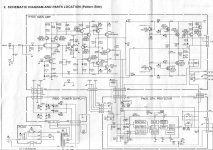
Strange things on those circuit diagrams, P-channel MOSFET 2SJ115 were connectet up side down and drawn as N channel.
naah
usual mistake
anyway - who's going to make da thing from scratch - is able to even ignore that type of mistakes
in any case - tnx for pointing that
@jeffreybehr :
if you are willing - send me full res pic to >sasica5@gmail.com< , and I'll edit it , shrink adequately , and post here
usual mistake
anyway - who's going to make da thing from scratch - is able to even ignore that type of mistakes
in any case - tnx for pointing that
@jeffreybehr :
if you are willing - send me full res pic to >sasica5@gmail.com< , and I'll edit it , shrink adequately , and post here
if you are willing - send me full res pic to >sasica5@gmail.com< , and I'll edit it , shrink adequately , and post here
Isn't that what I just did?
well , you certainly did 
what I meant - please send me high res ....
and then I'll edit that drawing mistakes for Q718 & Q720 , and post edited schm here .....

what I meant - please send me high res ....
and then I'll edit that drawing mistakes for Q718 & Q720 , and post edited schm here .....

Am almost finished with improvements. If you care, I've posted some info and pics in my blog... http://jeffreybehr.myblogsite.com/
The output-stage powersupply ended up, per pole, with the original 'ELNA for Audio' 22000/50 plus 2 times 2200/35 BG-VKs, a 100/50 BG-K, and a '1.47' uF SoniCap Platinum. Voltage-gain PS* ended up with, per pole, a 680/65 BG-F, a 100/100 BG-std, a 47/100 BG-std, and a '0.517'uF SoniCap Platinum. Both rectifiers are now sets of Fairchild Stealth diodes. Have replaced decoupler C710 with a 470/16 BG-VK, Rs757-760 and R765 with Mills MRA-5s, C708 with a MultiCap RTX 0.1/200, and will replace R771 and C712 when I remount the Cardas bindingposts. I have some UPOCC stranded 14g. wire coming to replace internal PS wiring; I'll use AQ's silver-over-OFC-copper spades on those. Captive powercord is a twisted pair of solid 12g. UPOCC copper in PVC with a Furutech FI15MER (rhodium over OCC copper) plug. I stand each amp on 3 Herbies Tall Tenderfeet.
The system now sounds breathtakingly smooth--NOT gritty or edgy--AND transparent...the best it ever has. This has been worth all the money and time I've spent on it. 😀
* The schematic show 3 times 470s per pole; actual was one 1000/63 ELNA per pole.
Those are xlr connectors? I own ma 24s and they need an update after +20 years of good service...
Thanks
Thanks
ma 24 service manual
hello,have someone service manual?I'm looking to find how to set up bias setting and offset.can you help me?Thank you
hello,have someone service manual?I'm looking to find how to set up bias setting and offset.can you help me?Thank you
as I wrote in PM :
offset 0 - set with pot marked as R714
Iq - set to 167mV across source resistor (any of them) , with pot marked as RN51
if that's not enough - post pictures of amp in thread and we'll help
offset 0 - set with pot marked as R714
Iq - set to 167mV across source resistor (any of them) , with pot marked as RN51
if that's not enough - post pictures of amp in thread and we'll help
- Status
- Not open for further replies.
- Home
- Amplifiers
- Solid State
- Marantz MA-24...the quad was received last nite.