Hi
I have a very tidy Marantz CD 50 with an issue I can’t bottom out.
The deck won’t eject from the button on the front panel or the remote control either. The motor is working and not faulty. I’ve put 5 or 6 VDC across it and working fine. I’ve also replaced the button on the display/control panel for good measure.
I’ve got the service manual but really struggling to get any ideas or a starting point from the schematics available.
Any help will be truly appreciated.
Thanks, J
Hi Julian,
There is a belt driven gear on the disc sled that very commonly strips teeth. The same part fits many models, so aftermarket ones are really easily available. maybe it's that, since you can hear the motor working.
I fitted one to my CD50se in about half an hour. Google CDM4 Tray Gear.
Stuey
There is a belt driven gear on the disc sled that very commonly strips teeth. The same part fits many models, so aftermarket ones are really easily available. maybe it's that, since you can hear the motor working.
I fitted one to my CD50se in about half an hour. Google CDM4 Tray Gear.
Stuey
Last edited:
Ahh, ok. I thought you meant the motor was running while in place, but the drawer wasn't popping out.
There are a couple of relevant parts from the service manual. Here's the schematic for the tray motor drive:

And here's the table including the expected behaviour at test point 83:

What I'm seeing from this:
Anyway, here's what I would check:
Another couple of voltages to check that shouldn't change:
Let us know what you see.
And here's the table including the expected behaviour at test point 83:
What I'm seeing from this:
- When the draw is not moving the voltage at 83 should be 2.5V. This is probably some sort of square wave signal with a 50% duty cycle.
- When the draw is opening this changes to near 0V, when the draw is closing this changes to near 5V.
- And then the TCA0372 power opamp inverts this and cancels the 2.5V offset, somehow, hmmm ...
Anyway, here's what I would check:
| Pin | Idle | Tray going out | Tray going in |
| 6530 pin 21 | 2.5V | 0V | 5V |
| 6504 pin 3 | 0V | 5.4V | -5.4V |
Another couple of voltages to check that shouldn't change:
- 6504 pin 4: -10V
- 6504 pin 2: 10V
- 6504 pin 6: 2.5V
Let us know what you see.
Thanks for this, just what I needed. I’ve got the unit back together at the minute but will take a look and measure and report back asap.
I am encountering problems with this TCA more and more often, and even if I have never had them on a CD player as simple as the CD50, I will focus on it directly if I encounter a similar failure.
An update, resistor 3545 has gone open on the 10v supply.
Replaced now door motor running continuously along with voltage on 6504 all over the place.
Pin 1 = 8v
Pin 2 = 8v
Pin 3 = 8v
Pin 4 = 6v
Pin 5 = 6v
Pin 6 = 6v
Struggling to track the -10v supply
Replaced now door motor running continuously along with voltage on 6504 all over the place.
Pin 1 = 8v
Pin 2 = 8v
Pin 3 = 8v
Pin 4 = 6v
Pin 5 = 6v
Pin 6 = 6v
Struggling to track the -10v supply
Ok, more progress. Found the faulty resistor on the -10v (r3546)
Now 6504 measures:
4 = -11.6v
2 = 9.7v
6 = 2.5v
3 = 0v
6530
0v at pin 21 at idle. Looks like this is where it’s failing. Any ideas guys
Now 6504 measures:
4 = -11.6v
2 = 9.7v
6 = 2.5v
3 = 0v
6530
0v at pin 21 at idle. Looks like this is where it’s failing. Any ideas guys
Okay, the 6504 power opamp is fed from the +10A and -10A supplies. This is the +10 and -10 supply through resistors 3545 and 3546. These resistors are a fusible type, and are designed to open if the power opamp fails, rather than potentially damaging the transformer. From this you can probably infer that the designers thought that there was a good chance the TCA0372 might fail.
Did you use fusible resistors for the 3545 and 3546 replacements?
From your measurements, I'm a bit concerned about the difference between pins 4 and 2. The +10A and -10A supplies are not regulated, so won't be exactly ±10V, but I think they should be more symmetrical. It makes me think something might be drawing quite a bit of current from the +10A supply. Can you check this by measuring the voltage across 3545 (and you might as well check 3546 as well)?
It would also be interesting to see the voltage at pin 5, to see if the opamp is trying to work.
From your original question I had assumed the CD player's tray was not moving, but otherwise the player was working okay - the tray motor is hardly essential. However, There was no power to 6504, and the other half is part of the laser focus drive circuit, which definitely is essential. So what is the CD player able to do? Is the display showing anything? Was it able to read a CD at some point?
Hi @amc184
There’s a bit of a story here (as always) around the 6504. I shorted this when testing after initially posting this thread and as such this had taken the fusible resistors down. I also believe I may have damaged ic 6500. So, I’ve replaced both ic’s.
So prior to starting this job (eject motor not working) all functions working correctly, cd player reading etc.
The fusible resistors I have replaced are normal 1/4w metal film. (3545 & 3546)
The voltages across the resistors are:
3546 = -11.5v
3545 = 9.6v
Voltage at pin 5 = 2.5v
I would recommend replacing 3545 and 3546 with fusible resistors. An example of what should be suitable:
https://www.digikey.co.nz/en/produc...oric-bc-components/PR01000101008JA100/1920078
When I said measure across 3545 and 3546, I meant the voltage difference between the two ends of the resistor. Because V=IR, this can give you an idea of how much supply current is flowing into 6504. Or you could measure between ground and both ends of 3545 and 3546 (four measurements total).
I assume that your measurements were taken at idle, when the player isn't trying to move the tray. If so, your measurements look okay, apart from maybe the difference between +10A and -10A.
Pin 6 should always be 2.5V ☑️
If the opamp is working pin 5 should also always be 2.5V ☑️
If the microcontroller is neither pulling pin 5 up or down through 3728 (by outputting 2.5V), then the output should be near 0V ☑️.
If you're sure that the voltage at 6530 pin 21 is 0V, then check the resistance between this pin and pin 5 of 6504. This should be 5.6kΩ, but if it is open this would also match your measurements.
What are the voltages doing when the player tries to move the tray in and out?
Hi @amc184 thanks for this and sorry for late reply, been flat out at work.
The link to the fusible resistors is very useful, I’ve struggled to find these in the past so thanks for this.
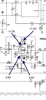
I’ve attached a screenshot of the measurements across the resistors as instructed.
There is no voltage changes at any of the pins on 6504 when pressing the eject button however the resistance between pin 5 at 6504 and pin 21 on the microcontroller 6530 is very high at 10 m ohm. Perhaps this is where the problem is.
Thanks again for your help here.
The link to the fusible resistors is very useful, I’ve struggled to find these in the past so thanks for this.
I’ve attached a screenshot of the measurements across the resistors as instructed.
There is no voltage changes at any of the pins on 6504 when pressing the eject button however the resistance between pin 5 at 6504 and pin 21 on the microcontroller 6530 is very high at 10 m ohm. Perhaps this is where the problem is.
Thanks again for your help here.
Attachments
High resistance between 6530 pin 21 and 6504 pin 5 is a problem. This should be 5.6kΩ, so I'd be checking 3822, 3827, 3828 and 3728 to see where the issue is. Also:
- What are you measuring at 6530 pin 21? I think you might have said this was always 0.
- Is the rest of the player now working okay?
@amc184 can confirm that all functions are working correctly. CD plays and all other functions.
Here are my measurements
3822 = 467mv
3827 = 500mv
3828 = 430mv
3728 = 500mv
All the above measurements drop to 0v when the eject button is pressed. All measure the same at both sides.
To confirm, pin 5 has a healthy 2.5v but drops to 500mv as soon as it arrives at 3728.
Also pin 21 has 328mv and drops to 0v when eject button is pressed.
Hope we’re getting closer. Thanks for helping.
Hi @amc184 Update on the above. I made an error measuring.
I should of reported that I have 2.5v on pin 4 and this drops to 500mv when arriving at 3728.
Also, I’m hoping this helps. I’ve just learned that when I power the machine on, I get 5v at pin 21 of the microcontroller for a few seconds, then it fades away to 0v and then a few seconds pass, rises back to 5v then back to 0v before settling at around 300mv. Only does this for 1 cycle
Last edited:
This doesn't sound great. You'll need to work out what's causing the high resistance between the microcontroller and 6504 pin 5. Even with that, the behaviour of pin 21 doesn't seem right, so it may have been damaged.
Ok, thanks for your assistance. Think I’ll need to park this one for now. The schematics I’ve got I’m struggling with and I have very little experience with microcontrollers. Thanks again, J 👍
- Home
- Source & Line
- Digital Source
- Marantz CD50 - Eject Button Issue - Motor OK