hello
If I may ask some advice here
I have a problem that I am wondering if I should try to fix myself or get serviced. I am in general pretty handy BUT very little experience with electronics.
my Marantz 1090 is making a really terribly loud and awful cracking noise. It sounds like this is a blown transistor? If so it seems like this is an easy fix, but not something I have done before. It's not that I have an aversion to getting it serviced by a professional, but I live in a very rural area and would have to expensively ship it, which I don't really want to do. So I am weighing how easy is that fix, how likely am I to mess up and make it worse?
Welcome to diyAudio 🙂
To answer your question... it may be an easy fix all the way through to something that is extremely difficult to diagnose with detailed test and measurement needed.
In the first instance the big clues are,
1/ One or both channels affected?
2/ Does it matter where the volume is set i.e can you turn the crackling down with the volume.
3/ All inputs the same or just one?
4/ Does it sometimes work normally, even if only for a second or two?
It could be something like a bad solder joint (a dry joint) or if on one channel an intermittent failing transistor or diode or perhaps a bad capacitor (not an electrolytic as first suspects though).
Hello
thank you
1. I am pretty sure it is both channels. It is extremely loud and I don't want to try it again to check for fear of blowing the speakers.
2. It is not effected by where the volume knob is set
3. all inputs
4. it was for a short while just happening a tiny bit here, a tiny bit there, but now it happens constantly
Hmm... interesting.
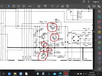
Both channels suggests a common power supply issue. So just looking at the circuit (and this is purely intuition without seeing it) and I would have a close look at the two 'series pass' regulator transistors and the components around them.
Have a really close look for bad soldering. Torch and magnifying glass if needed. The last images in post 1 of this thread show what they might look like where the solder cracks and forms a ring around the pins.
Sony CDP790 and KSS240 Restoration Project
I'll have more time to look tomorrow but this should get you started if you want to have a look.
Look all around that area on the board for any signs of heat (which isn't a problem in itself) because that causes the joints to fail.
Attachments
If you don't have test equipment, use only a pair of junk speakers, and add a series 1k resistor
on each speaker, to reduce the volume of the noise. You will likely need a voltmeter, though.
on each speaker, to reduce the volume of the noise. You will likely need a voltmeter, though.
ok thank you I will do this.
Perhaps it is only one channel, and just so loud that it is difficult to discern that it is only one. I would've tested that right off the bat but I don't have a pair of junk speakers around right now.
Perhaps it is only one channel, and just so loud that it is difficult to discern that it is only one. I would've tested that right off the bat but I don't have a pair of junk speakers around right now.
That's possible. Do you have some kind of voltmeter?
Anybody can make a problem worse, but beginners are usually more successful at it.
Anybody can make a problem worse, but beginners are usually more successful at it.
Last edited:
Perhaps it is only one channel, and just so loud that it is difficult to discern that it is only one. I would've tested that right off the bat but I don't have a pair of junk speakers around right now.
One or both channels is the vital question. If on both then it rules out all I said on the voltage regulators 🙂
I took a look at these spots and I see a lot of solders that are starting to crack/yellow. Nothing egregious but I think it is exactly as you are describing. There are other spots all around that are starting to look like this so I think whatever doesn't have to get done now will have to be done in the near future anyway. Considering that I don't have a voltmeter, I haven't soldered in 20 years, I think it would be best for me to not do this myself. Nothing looks terrible so I think it'd be an easy job for an experienced person. But thank you folks very much for your quick and informative replies. I've lurked here for a while and only now just posted but I think I will continue to poke around, especially considering I just bought a nice AR-XB that I would like to refurbish!
In my extensive experiences with vintage Marantz solid state stuff, it seems that I've come across issues in those products that had yellow jacketed electolytics in them - they always came up faulty.
Rip any yellow E-caps out and replace them.
Rip any yellow E-caps out and replace them.
I took a look at these spots and I see a lot of solders that are starting to crack/yellow. Nothing egregious but I think it is exactly as you are describing. There are other spots all around that are starting to look like this so I think whatever doesn't have to get done now will have to be done in the near future anyway. Considering that I don't have a voltmeter, I haven't soldered in 20 years, I think it would be best for me to not do this myself. Nothing looks terrible so I think it'd be an easy job for an experienced person. But thank you folks very much for your quick and informative replies. I've lurked here for a while and only now just posted but I think I will continue to poke around, especially considering I just bought a nice AR-XB that I would like to refurbish!
Fair enough, if its a treasured possession I can understand not wanting to cause further issues. A decent multimeter is absolutely essential as well for any kind of diagnostic work... maybe for the future 😉
Good luck 🙂
- Home
- Amplifiers
- Solid State
- Marantz 1090 repair question