Hello, I am in the process of buiding my first true audiophile amplifier and I have many questions for you and will appreciate any answers 🙂
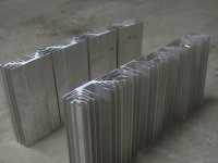
Today I have cut my heat sink bar in 8 sections of 9'' and will assemble the chassis like the picture. I have used a 10'' Freud aluminum saw to do the job.
My goal is to build a no-compromise amplifier.
Following are my questions:
1. How can I polish the extremity of the heat sink section and which tool should I use to do the job (preferably by hand)?
2. What is the best diode bridge I can use for the power supply?
3. I plan to mount one transistor on each section of the heat sink, what kind of wire should I use to connect the transistor to the PCB? Gauge? Silver? Solid?
4. What kind of wire should I use for signal path (input and output) and where I can buy them?
5. Power supply: should I use the original design or should I build a PI filter?
6. Is is a good idea to use WBT silver solder to populate the PCB and make the wire connection?
I am sure there is more to come...
Thanks!
Attachments
Zen Parts
Each weekend I get a little more done on my own Zen V4. Here are my own misguided opinions on this.
For the diode bridges I used some 200v, 20A MUR discrete diodes to build some better quality bridges. Used the same for the bridge going to ground.
Look at the recommended power supply. The listed 50v caps before the regulator are very marginal. I used a 10,000 ufd 63v, 4 ufd choke (.23 ohm DCR), 10,000 ufd 63 v cap CLC filter. THis may be an improvement over the power supply listed.
The wiring is not critical for the power supply and using solid core of a guage heavy enough for the currents would stress the solder connections. Some 16 guage stranded wire should work great for high current wiring. The signal path wire is a personal thing, but I am using a XLO solid core sourced from Michael Percy. The 26 ga is great. I thought of using the Vampire CC magnet wire for this too, but I do not think it would have much effect.
Wiring up hard wire looks good, but I purchased the boards from PassDIY. This hould help with hum, but the low impedances seen in the circuit help even more.
Once yours is done let us know. If my wife, kids, and job would give me a whole day to work on it mine would be playing. But getting a hour here and there it may be a few more weeks.
Tapping the holes in my heatsinks has been the most frustrating part. I have broken a few off now. I think Ineed to back them out more often to clean the threads. But live and learn.
George
For the wire I'd reccomend solid enameled magnet wire, a thicker gauge makes it easier to work with, since it's solid it'll hold it's shape and is easy to neetly place in the chasis. Apparently some say it "sounds" good too, but to me wire is wire. As for the bridge, go with a good 35A bridge, with big caps you don't want to blow up your diodes (the smell of burnt diodes sucks when they're discrete and you spent forever setting them up neetly in the circuit and raplacing them is tedious).
since it's your first amp, i'd purchase the boards and Q-pack
from pass DIY. Of course with that setup you mount all 3
MOSFETS to 1 heatsink... maybe to late since you already cut
your sinks?
not that i'm a pro at building amps, but anything to make the
process easier is always a plus in my book! Having the whole
Zen V4 article to help build the amp is huge too.
just my thoughts...
m.
😱
holy moly francois. that's gonna be one intimidating-looking amp.
for question #1, i imagine you could use an orbital sander, or a belt sander. only thing is, i don't know what kind of sandpaper you should use.
if the surface looks okay already, and all you need to do is remove burrs from the edges/corners, then you could probably just use a grinding tip on, like, a drill or a dremel maybe.
hope that gives you some ideas anyway.
wow, 8 heatsinks - are you doing 4 channels, or just 2? i thought there were only 2 transistors per channel that produced much heat...?
you don't have any leftover pieces you want to get rid of do you? 😉
/andrew - can't wait to see this one put together
Thanks for your answers.
Moe29, I have already bought the PCB from PassDIY because this is the only way to reward Nelson and to encourage him to continue to support the DIY community.
I think it is a better idea to separate each transistor to spread the heat dissipation among several heat sinks. I have look at the Zen V4 published on the passdiy site and they are nice but I think they all suffer from overheating. I think this is the best approach unless you spend big money (> 200$ US) on a custom heat sink.
Do all 3 of the heatsink mounted MOSFETS dissipate the same
amount of heat? For some reason i thought Q1 runs the hottest.
...maybe i'm totally off base.
i see!... i think i remember Mr. Pass saying in one post that you
could separate the MOSFETS from the board up to 6" or so...
but that's just off of memory. Maybe you could mount the board
and one MOSFET on one heatsink and then use wire to connect
the other 2 to sinks on the left and right...
it's late, i should crash, mostly i just wanted to say good luck
and keep us posted - with pics! 🙂
m.
If I remember well, two of them are dissipating a lot of heat and the third one is not dissipating a lot. There a thread on this, but I am lazzy to search and give you the link. Since all the four section will be connected together with aluminum, I think it should also act as a big heat sink.
moe29 said:Do all 3 of the heatsink mounted MOSFETS dissipate the same
amount of heat? For some reason i thought Q1 runs the hottest.
...maybe i'm totally off base.
i see!... i think i remember Mr. Pass saying in one post that you
could separate the MOSFETS from the board up to 6" or so...
but that's just off of memory. Maybe you could mount the board
and one MOSFET on one heatsink and then use wire to connect
the other 2 to sinks on the left and right...
it's late, i should crash, mostly i just wanted to say good luck
and keep us posted - with pics! 🙂
m.
Since current is about 2 A and the voltage drop in the regulator is a little less than 10 V and the voltage drop in the amp is about 20 V per transistor it works out as roughly 20 W for Q5 as the regulator transistor and 40 W each for Q1 and Q2 in the amp part. That makes up the 100 W total dissipation.
Here is the thread: http://www.diyaudio.com/forums/showthread.php?s=&threadid=12550
Any others answers for my specific questions?
Any others answers for my specific questions?
François said:3. I plan to mount one transistor on each section of the heat sink, what kind of wire should I use to connect the transistor to the PCB? Gauge? Silver? Solid?
Thanks!
For those interested: the answer from Karen is: 16 gauge stranded copper wire. They have tried it.
Any other answers to my question will be appreciated.
Thanks
PI FILTER
i too am planning to use a pi filter on my power supply...i have a bunch of 10,000uF caps ready for action. only 50v though. 🙄
Panelhead: i've searched for the thread that discussed the recommended coil parameters; do you know where it is? i couldn't remember if it was 2-4microH, or 2-4milliH. BTW where did you obtain your coil? how hard is it to make a good one?
/andrew
I did a lot of simulations using Duncans Power Supply Designer and came up with 18,000 uF, choke, 36,000 uF (2 each 18,000). ( Caps are Panasonic from DigiKey, and I wanted to use all same kind)
I keeping with some of the junkbox approach, I used a choke from an old UPS which is approx 0.5 mH, .2 ohm. The actuall ripple was very close to PSU's results when I tested into a 2 Amp load. (Piltron xfmr).
I am waiting to get heatsinks to go to the next phase - the 3"x3" sink I am testing with needs a LOT of fan to keep it below 150 F.
I am using 4 MUR diodes in a bridge.
My initial testing using Mr. Nelsons kit showed that the Zen needs a very good power supply - I thought I could use a 40 Volt 12 amp xfmr I had but it was too noisy - hummed way to loud.
WBT Solder or other
Hi Francois. Good Hi-Fi show in Montreal. To answer your question about the WBT solder, I use 2% silver solder that I buy from ABRA, 731-0117.
It is cheaper and give me very good result....
Bye...
Hi Francois. Good Hi-Fi show in Montreal. To answer your question about the WBT solder, I use 2% silver solder that I buy from ABRA, 731-0117.
It is cheaper and give me very good result....
Bye...
Chokes
I lucked into the 4 mH chokes with a DCR of 0.23 ohms. They were on a shelf at a local electrical supply shop. The rating is 4 amp, but I am running my Zen at 1.25 amp. Best of all they were 5.95 each. But a return trip saw all the nice chokes had vanished.
BTW, if you build the power supply as shown you should get 52 -53 volts on the filter caps. I used a single transformer 300VA with 38/38 winding to allow using one for each channel. Should get 55 - 56 volts from the raw supply.
With the lower current I hope to get by with a 7 1/2 x 4 3/4 x 2 1/2 heatsink per channel. The back is thick and the fins thin and close spaced. Found them at Tanner in Dallas for 6.95 each. A trip up six weeks ago they were all gone, but yesterday they were back in stock at 5.95. Had to get another pair for a 10 watt Aleph planned for next year.
Also found some SuperBrite 5mm Blue diodes for 1.99 each at Tanner's. They demonstrated them with 10 ma and they almost blinded me. Had to buy some.
George
Re: WBT Solder or other
Do you know if the 5% silver for plumbing is the same thing?
Montreal Hi-Fi show, I will be there 🙂 Probably tomorrow from 13h to 21h. This is bad that we don't have a DIYAudio t-shirt to reconize DIYers.
Algar_emi said:Hi Francois. Good Hi-Fi show in Montreal. To answer your question about the WBT solder, I use 2% silver solder that I buy from ABRA, 731-0117.
It is cheaper and give me very good result....
Bye...
Do you know if the 5% silver for plumbing is the same thing?
Montreal Hi-Fi show, I will be there 🙂 Probably tomorrow from 13h to 21h. This is bad that we don't have a DIYAudio t-shirt to reconize DIYers.
A couple thoughts:
1. N.P. recommends that the choke used in a CLC supply be 2-4mH. You can get a 2 mH air core from Zalytron(.com) in 14Ga. for about $12. I think a Pi filter can only help, and not hurt the amp. It will provide additional filtering.
2. F.B.: I think your 50V caps should be just fine, unless you have a transformer that is >36V. They are unlikely to blow up if you're 0.1V in excess of 50V. Give them a go!
3. Wire: I haven't conducted any comparative listening tests. I think that those with better ears than I might suggest pure Oxygen Free Copper (OFC) solid. I'm using silver plated stranded copper (that's just about the opposite), 16 or 18Ga, with teflon insulation (Apex Jr has it) and think it sounds fine.
4. Want to read about diode bridges and fast/soft diodes in the supply? Read here: http://www.diyaudio.com/forums/showthread.php?postid=134303#post134303
5. Francois: I suggest that you use a belt sander to finish the cut ends of your heatsinks. You should apply some oil to the aluminum first. This will make the finish nice and prevent the aluminum from galling. Use something like 36 grit to get a nice brushed look. With the oil, it gives a finer looking finish than you would expect with such a coarse belt. See below.
6. Blue LED's: You may find that ultimately you are struggling to find one that won't blind your music-listening guests.
I looked at digikey's site and if you search under Blue LED you can get a bunch of choices. I bought 2 ea. of several of the LEAST bright ones. Even then, it took a bit of fiddling with the series resistor to get the brightness down to reasonable levels. Super-Bright looks a bit too DIY for my tastes.
Edit: I wonder where my belt-sander picture went?

heatsinks
...i wonder if they'd be willing to ship? that's a good price for that size heatsink. any idea of the °C/W rating?
/andrew
Panelhead said:....With the lower current I hope to get by with a 7 1/2 x 4 3/4 x 2 1/2 heatsink per channel. The back is thick and the fins thin and close spaced. Found them at Tanner in Dallas for 6.95 each. A trip up six weeks ago they were all gone, but yesterday they were back in stock at 5.95. Had to get another pair for a 10 watt Aleph planned for next year.
....
...i wonder if they'd be willing to ship? that's a good price for that size heatsink. any idea of the °C/W rating?
/andrew
just to be really dense:
so, that's milli-H, not micro-H.
vpharris said:....
1. N.P. recommends that the choke used in a CLC supply be 2-4mH. You can get a 2 mH air core from Zalytron(.com) in 14Ga. for about $12. I think a Pi filter can only help, and not hurt the amp. It will provide additional filtering.
....
so, that's milli-H, not micro-H.
- Status
- Not open for further replies.
- Home
- Amplifiers
- Pass Labs
- Many questions on Zen V4