Hi Y'all,
Anyone have a manual, schematic, service information for the
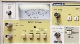
Panasonic VP-7635A. It's a FM Multiplex Generator.
In need of assistance and the one place that had one
donated everything to the Web Time Machine thing
never to be seen from again. 🙁
Cheers,
Sync
Anyone have a manual, schematic, service information for the
Panasonic VP-7635A. It's a FM Multiplex Generator.
In need of assistance and the one place that had one
donated everything to the Web Time Machine thing
never to be seen from again. 🙁
Cheers,
Sync
vp-7637a_outline.html
This is all I can find on it.
@JonSnell, Thanks for looking. I found that, too. I contacted him
and aksed if he had a manual, schematic etc to no avail.
I also found something written in french for the VP7635a.
But not what I was looking for.
Another DIYer was kind enough to send me a manual for a VP8174a
unit in hopes it might assist me. The actual units are so dissimilar that
I can't use it to trouble shoot or work from on my VP7635a with my
limited background. There are some good GPIB code examples though.
It is what it is.
Cheers,
Sync
3 of the 4 Latching Switches are broken, won't latch.
I think they are called Shadow Switches?
The guy I got it from, didn't notice the Outer Rings were removed
when cleaning the unit.
Then I'm pretty sure the same cleaning guy also turned the
calibration pots when he removed the stickers from them.
When I opened it up to inspect, it looks fine inside, and showed
no signs burned parts or over heating etc. So I put it back together
to try and figure out why only the 19kHz tone worked and none
of the other tones, etc.
Only to discover that when I pressed and held in (a certain amount)
I would see the tone on my scope. Then I reexamined the switches
and discovered 3 didn't have the ring that would hold the latch mechanism.
These switches control the External and Internal Tones,
which left or right channel is internal or external, during
dual tone mode, or/and which single tone is internal or external.
EXT - Good
L - R
Dual Tone - Bad
INT L
EXT R
SINGLE TONE
EXT - Bad
INT - Bad
I'll attach a pic.
If I had three other switches or the applicable latch hold mechanism
then I could see what else would need to be accomplished to get this
instrument running correctly.
Cheers,
Sync
Attachments
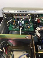
I had the same issue before, it's not the TC9135 analog switch but a faulty 74xx244 tri-state buffer that ultimately drives the control lines for the TC9135. U35 and U36 are likely bad.
The latching of the push button switches is done electronically.
The latching of the push button switches is done electronically.
Last edited:
I had the same issue before, it's not the TC9135 analog switch but a faulty 74xx244 tri-state buffer that ultimately drives the control lines for the TC9135. U35 and U36 are likely bad.
@ hitachi, are we discussing the same model, the Panasonic/National VP-7635a?
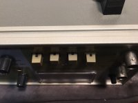
These are four latching switches of which three of them no longer have
the part that keeps them latched. I presume that is the rim around them.
Only the first on the left will physically latch when pushed in.
The other three, want to latch but they are missing outside piece
or rim which should hold it in the latched position.
Now, I cannot answer about their electronic function other than
it is possible in that latch position it also functions as a relay?
And whatever voltage that should be there to hold the switch
in the latched position breaks, because there is noting physically
to retain it.
The other push switches that you describe are those the non-latching
switches that illuminate when pressed?
For this model the latching of the push button switches is
also done electronically?
I don't know as I don't have a schematic.
Please understand I'm not arguing, I just want to ensure that when I
start pulling and replacing parts that the problem doesn't remain.
On other models that I've seen of this meter they ALL have the
rim around the switch on these first four latching switches.
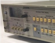
Attached is a pic of the VP-7633, which also shows the different
switch types. The four on the left are the latch switches. Besides
these four and the power switch, all the other push switches are the
standard Panasonic/Matsushita/National electronic type. The ones
with the lamps in the center.
The follow on model to my VP-7635a is the VP-7637 which doesn't
have the latching switches any longer. I just have to be sure on this.
Cheers,
Sync
Attachments
Last edited:
Duhh. I was thinking of the soft switches that are electronically latched that get stuck electronically. Sorry.
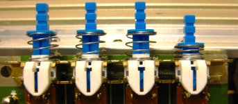
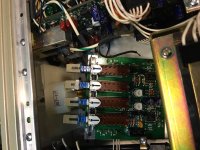
OK now to the mechanical latches, when you have the rightmost ("INT") of the group of four pushbutton switches pushed in, does the output drive the selected internal frequency (30Hz to 15kHz)?
Here's my unit's 4 pushbuttons with "INT" engaged. I don't see any outer ring mine.
OK now to the mechanical latches, when you have the rightmost ("INT") of the group of four pushbutton switches pushed in, does the output drive the selected internal frequency (30Hz to 15kHz)?
Here's my unit's 4 pushbuttons with "INT" engaged. I don't see any outer ring mine.
Attachments
Duhh. I was thinking of the soft switches that are electronically latched that get stuck electronically. Sorry.
OK now to the mechanical latches, when you have the rightmost ("INT") of the group of four pushbutton switches pushed in, does the output drive the selected internal frequency (30Hz to 15kHz)?
Here's my unit's 4 pushbuttons with "INT" engaged. I don't see any outer ring mine.
@hatachi, No worries, that is why I asked, to be sure.
Now the function or lack thereof, It is supposed to, yes. But, that push button doesn't engage and stay in. I have to hold it with my finger manually on the engagement point, then I can press the soft switch and then I can see the Tone on the output.
Now, I'm not sure if the output drives the selected internal frequency.
I assumed there was and internal oscillator in the unit. If that is what
you mean by the output drive then yes.
I think I can only view the opposite side side of the pushbutton switches,
the latching is on the other side. I'd have to disassemble the unit more
to see. I want to say they have the bronze latches and the latches you
show are the newer plastic style.
Cheers,
Sync
Last edited:
Got some other pics of the latches. They are same as yours I believe.
With the white plastic. I think the latch is on the board side.
I didn't remove mine, didn't know if two or four screws plus
desoldering a few leads. It looks tight to get in there.
Cheers,
Sync
With the white plastic. I think the latch is on the board side.
I didn't remove mine, didn't know if two or four screws plus
desoldering a few leads. It looks tight to get in there.
Cheers,
Sync
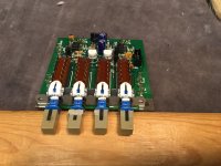
Are the switches supposed to be interlocked? There are some sliders in the mechanism that handle the latching and the interlock. Those are probably very similar to the US switches but not interchangable. The interlocked switches have a single spring loadaed slidre that is moved by a cam on the switch. The individual ones have seperate little loops of wire that follow an eccentric slot in the side of the switch shaft. Yours may have a locked slide from who knows what. You can sort of see the spring in the picture above that returns the slide to lock the switch in place after releasing all the others.
Demian, I don't know as I don't have a manual and I don't have access to a working switch group.Are the switches supposed to be interlocked? There are some sliders in the mechanism that handle the latching and the interlock. Those are probably very similar to the US switches but not interchangable. The interlocked switches have a single spring loadaed slidre that is moved by a cam on the switch. The individual ones have seperate little loops of wire that follow an eccentric slot in the side of the switch shaft. Yours may have a locked slide from who knows what. You can sort of see the spring in the picture above that returns the slide to lock the switch in place after releasing all the others.
@hatichi, Are those switches are they from a VP7635a? or VP7633? Should be same I think. Are yours fully functioning? Are they as Demian described?
I'm wondering how to find another switch set or fix these. But first it
would help to have a part number. or Know how they are supposed to
function. 🙂 Or Figure out how wrong the ones on my meter are.
They aren't fully functioning as they are. I don't want to dig in there just
yet and have little parts falling out. Or another piece of gear that is
non functioning laying around in parts. Not that I do that anyway.
It would definitely help to have a working unit or working switches.
Pics at Six,
EDT
Attachments
Last edited:
Demian, I don't know as I don't have a manual and I don't have access to a working switch group.
@hatichi, Are those switches are they from a VP7635a? or VP7633? Should be same I think. Are yours fully functioning? Are they as Demian described?
EDT
I have the VP-7635P, I took out the P sticker that was affixed on top of the 'A'. Now my unit is a VP-7635A 😀 It's fully functional.
The pic I sent with the switch taken out from the chassis was done by doing the following steps:
1. remove the bottom cover
2. remove the 2 screws that hold the switch bracket
3. remove the 2 screws that holds the switch and bracket
4. pull out the 4 switch caps
5. pull the 2 connectors on the board
Last edited:
hatachi,
With the bottom removed and upside down on the bench,
What role does the rim around the switch cap play?
To get at the latching part I assume they need to be desoldered
from the board?
on the board before removing it. I'll get there.
When I get to that part I'll take some pics and go from there.
Cheers,
Sync
With the bottom removed and upside down on the bench,
These would be the two screws along the case (bottom)?1. remove the bottom cover
2. remove the 2 screws that hold the switch bracket
These are the screws that screw into the back side of the faceplate?3. remove the 2 screws that holds the switch and bracket
Is there an insertion device for these? or do these just slide off?4. pull out the 4 switch caps
What role does the rim around the switch cap play?
To get at the latching part I assume they need to be desoldered
from the board?
I didn know if I needed to desolder the other connections5. pull the 2 connectors on the board
on the board before removing it. I'll get there.
When I get to that part I'll take some pics and go from there.
Cheers,
Sync
@hatachi,
I was hoping to do this w/o having to desolder the
other connectors, etc. If I don't desolder them, well
we know what that's like, turning the board over and
back a few times starts causing broken wires or worse
the dreaded intermittent.
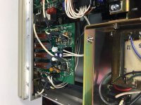
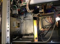
Here pic. The hard part for me would be reaching into
step 3 to get those screws loose and pull the board with
out breaking, losing, dropping stuff. Oh, but this IS
electronics. 🙂
I appreciate the assist.
Cheers,
Sync
I was hoping to do this w/o having to desolder the
other connectors, etc. If I don't desolder them, well
we know what that's like, turning the board over and
back a few times starts causing broken wires or worse
the dreaded intermittent.
Here pic. The hard part for me would be reaching into
step 3 to get those screws loose and pull the board with
out breaking, losing, dropping stuff. Oh, but this IS
electronics. 🙂
I appreciate the assist.
Cheers,
Sync
Attachments
Well that was fun. Mine only has the Step 3. screws.
Step 4 couldn't be accomplished.
Step 5 could.
Step 6, tried Step 4 again but couldn't get the board out.
So desoldering it was. Then there was a surprise under the board.
Another set of leads also needed to be desoldered.
Then the board came out.
Then step 4 and the problem was obvious.
The "Tech" had tried to repair the switches
by super gluing the ring around them.
AND
Demian described the switches the way they work,
interlock and latching. So I pulled off the caps
and chiped off the glued on ring parts.
VuaLua...
Took a bit longer to get them back in but I managed to get there.
Next step, how are they supposed to work?
How is it suppoed to work?
Pics at 6 maybe 11?
Cheers,
Sync
Hitachi? How does it work? What should I do next?
Ill send a pic tomorrow. Please post pics of the switch. I mathave a spare. I bought a pile years ago to fix instruments. Need to know number of segments, center to center number of tabs (photo will show) and pin spacing so to fit pcb.
Sent from my LG-H811 using Tapatalk
Sent from my LG-H811 using Tapatalk
Pics at 11:00 EDT
Here are the pics, kind of a tight little spot that is.
My leads must be shorter than hitachi's as there was
no way to remove that board without desoldering
unless breaking off leads in tighter places counts.
I'm thinking the rim piece is probably more important
that many realize. With out it the switch button interferes
with the face plate and the back pieces. With the rim piece
the buttons rest and ride on it. The plastic on plastic is smooth
and doesn't catch on the cut out/punch out of the chassis.
I'm sure I could use them Demian, thanks for looking.
Cheers,
Sync
Attachments

Sync,
I've been busy with other things and haven't checked this thread for days. It will be days before I can open my unit. Why not open up a similar pushbutton from a parts pile and learn about the innards? These usually have a small metal hook on a spring that follows a cam which makes up the latch. I find it hard to believe that the switch failed, maybe the glue was applied to prevent others from changing the default setting of the previous setup.
I've been busy with other things and haven't checked this thread for days. It will be days before I can open my unit. Why not open up a similar pushbutton from a parts pile and learn about the innards? These usually have a small metal hook on a spring that follows a cam which makes up the latch. I find it hard to believe that the switch failed, maybe the glue was applied to prevent others from changing the default setting of the previous setup.
Last edited:
Sync,
I've been busy with other things and haven't checked this thread for days. It will be days before I can open my unit. Why not open up a similar pushbutton from a parts pile and learn about the innards? These usually have a small metal hook on a spring that follows a cam which makes up the latch. I find it hard to believe that the switch failed, maybe the glue was applied to prevent others from changing the default setting of the previous setup.
I would, but I don't have any other switches.
I can afford to ruin what it already in there either.
They may very well work now as intended, almost.
The buttons wouldn't go in or out and got hung up
on the face plate. Look at the pic that shows the button
half in and out.
The buttons still get hung up on the face plates but at least now
have a fighting chance of working.
The mounting is slightly different than yours as that frame I think
is soldered to the board or tack welded. If you look at my pic then
you'll see the switches have the frame bent to hold them too.
I don't need you to take yours apart, I just need to know how to test
mine to see how it works. Then I'll know what is broke.
With out a manual and without experience in FM MPX alignment and their
tools, I'm up the creek w/o a paddle. I also don't like what I'm hearing ahead
it sounds like a water fall close to the horizon.
Last edited:
- Status
- Not open for further replies.
- Home
- Design & Build
- Equipment & Tools
- Manual 4 Panasonic VP 7635A ?