Hi there
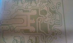
I have done a pcb with a inktjet printer, when you do print color grayscale and not use the black cardtridge, (on special folie from ebay in my case) do make good prints even when it is not complete dark, the yellow do block the uv making nice outcomes.
I have do with this pcb extreme test, I did lighting it for over 10 minutes, let it 15 minutes in solution give this, very nice, this means the grayscale do block uv light very well even if it seems not dark, it does, over lighting did not ruin it.
photo is made with mobile phone so it is not complete sharp, but it is as sharp as a inkjet can. even when print only yellow it works I think, this I go try soon.
regards
kees
Attachments
Last edited:
Here you can order.
20 Sheet Screen Printing Transparency Inkjet Film Paper PCB Print Stencil Design | eBay
works fine but print in grayscale, not black cartridge let me now how it works.
regards
20 Sheet Screen Printing Transparency Inkjet Film Paper PCB Print Stencil Design | eBay
works fine but print in grayscale, not black cartridge let me now how it works.
regards
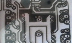
Have you tried using black ink and inkjet transparancy? And this greyscale method is better?
Yes I have, with black if shines through (particles) with gray not because yellow do block UV, I want to try yellow alone to see if that holds.
As you see I did light pcb very long and still it did came out well, I have heard from someone that yellow is the way to go, I did now use three colors to make gray. You need dye ink, not pigment.
see picture, not so sharp because of mobile phone.
Attachments
I still don't really understand how the yellow blocks the light better than the black. My main problem has been with etching the PCB anyway. Need a hot bubble etch tank really.
Where do you buy your negative coated PCB? Usually they are positive coated. I have also experienced tiny failures/scratches in the coating which again causes problems etching the PCB. I was thinking to try dry film.
Where do you buy your negative coated PCB? Usually they are positive coated. I have also experienced tiny failures/scratches in the coating which again causes problems etching the PCB. I was thinking to try dry film.
I have buy the pcb in our local electronics store and I have buy on a marked a package of this pcb who is big package.
I have also dry film, it takes less ink, you can use this print also for that I think dry film is also sensitive for uv, I do put dry film om pcb under water, that give than after through a laminator a nice pcb.
As far I do see and read, magenta and Yellow blocks UV , for me it works, black do over light it.
regards
Last edited:
This is not as daft as it may appear, in the old days of PCB production working phototools were bromide prints (a reddy brown appearance) that would block the UV light. The advantage over solid black was they were semi transparent so you could line up things easier...
I have found a nice place for stuff to make copperchloride, the best way to make pcb and not expensive, I can do a livetime with it.
Werken met Merken
Werken met Merken
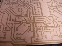
I have done a new one with inkjet using only color cartridges in gray scale settings photo and using glossy photo paper, however my epson dx8400 refuses transparancies so I need to trick the printer by gleu a transparanty on paper.
it do wel as I see, I did light the pcb with UV for 10 minutes, this is very long without damages.
it do wel as I see, I did light the pcb with UV for 10 minutes, this is very long without damages.
Attachments
I did have a issue with the negative resist, it go of difficult after exposure, in my case 2 minutes, I think the lamp is to close, I have used a normal tube exposurebox with 5 uv tubes in it who are quite close to the artwork, so it possible do go a little under the traces and make trouble.
I have order 200 uv leds and go make a box special for these negative resists.
because of it do not develop completely etching go wrong .
regards
kees
I have order 200 uv leds and go make a box special for these negative resists.
because of it do not develop completely etching go wrong .
regards
kees
I found that the trick is to stack 2 or more copies. That makes the dark parts denser. This also works with laser printed or pen plotted art.
I found that the trick is to stack 2 or more copies. That makes the dark parts denser. This also works with laser printed or pen plotted art.
The inkjet plots night black, no light do pass, i have tryed with a 1000 watt lamp it do shine very very little through. Because of small lines it has to be furhter away from the lamp who is a normal light tubes for normal pcb exposure.
regards
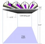
Collimating Your Light Source
I, too, had troubles with a simple light box as a source. Collimation is a big deal. I modified my light box by adding an "egg crate" style lighting grid between the tubes and the artwork to collimate the light. See the THINK & TINKER website for the how to .....
Home Built UV Exposure Head
Worked very nicely, solving my problems.
Alternatively I use a 3 watt UV LED as a point source. It, also, works well.
Bill
You has also that it has left parts of lighted resist what stay on pcb give ets trouble? thanks for the tip.
I have received now also 200 uv leds to make a box, these leds do also have point source.
regards
I have look at it and saw that the lamps are 13,5 inches above workpeace, my problem is the box is just 5 cm above workpiece and so I can not use collimation grid the right way?.
Special for negative resist it is needed distance is min 5 inch above workpiece, or film.
regards
Special for negative resist it is needed distance is min 5 inch above workpiece, or film.
regards
Attachments
Rotate The Grid
Cut the grid so that it is rotated about 45 degrees. Then you can simply set the grid on top of the tubes, Works nicely. I cut the grid with my table saw ... wear a face guard as plastic chips will fly!
Quote from THINK AND TINKER:
"Rotating the grid so that the rows of cells form an angle of 30° to 45° with the tube axes will eliminate Moiré fringes altogether and allow to collimating grid and copy board to be positioned wherever is most convenient. However, trying to cut the fragile grid material on an angle will significantly increase the difficulty of fabrication."
Bill
- Status
- Not open for further replies.
- Home
- Design & Build
- Software Tools
- making pcb negative with inkjet.