I figure this is a good spot as any for this question; I imagine it is VERY simple straight forward.
I have twelve 8ohm 100w resistors.
I want 8ohms resistance, but higher power dispersion capability.
Seems the only combination is a 2s2p combination and that would yield 8ohm, 400w.
Am I using the math correctly? The part am least sure of is the power dispersion capabilities being independent of the circuit. i.e. if the circuit has 400watts of resistors, that is the max it will disperse.
getting more specific; with a 2s2p resistor set up, does polarity start to come into play with respect to power dispersion?
with the resistor value I have (8ohm 100w), is 2s2p with negative connected to the 2p side mean the Max power dispersion is 200w / 400w or still just 100w?
Why not three series, three parallel? 3 * 3 = 9 <= 12.
The power will distribute equally between the resistors, so with three parallel strings of three series-connected resistors (or the other way around), the maximum dissipation is 900 W - assuming the heat from each resistor doesn't increase the temperature of its colleagues too much, that is, that they are not mounted too close.
The power will distribute equally between the resistors, so with three parallel strings of three series-connected resistors (or the other way around), the maximum dissipation is 900 W - assuming the heat from each resistor doesn't increase the temperature of its colleagues too much, that is, that they are not mounted too close.
Perfect! That confirms my understanding is at least practical lol
I had missed mentioning my target power dispersion was 300w.
Kind of a big figure to have missed mentioning lol
But indirectly I think you've confirmed that I cannot get an 8ohm 300w combination.
When ordering the resistors I had thought I could just put three in parallel and get 8ohm 300w and make four circuits to be able to test four channels at once.
I wish I had a need for 8ohm, 900w dummy loads lol
Thank you for letting me know the power dispersion would be equal; (fundamentally that seems to be the electron flow probability of a resistor is independent of other resistors in the circuit, obviously from that perspective)
300w would give me plenty of room, 400w is too much. But seems that is the next lowest power dispersion capacity I can achieve with 8ohm resistance given those resistor values (8ohm / 100w).
omg I did not think of proximity when mounting the resistors lol not a huge deal (because I'll need to wire as 2s2p and that is at least 100% headroom for the amps I would be testing) but I do have them mounted in groups of three...that poor middle resistor lol. I'll need to monitor that weak point; thank you for mentioning that aspect.
Last edited:
I completely agree with the above- but do note, a 100W resistor will require a decent heatsink to dissipate its rated power. 400W of test load requires reliable cooling if you are going to approach its full capacity.
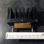
You can cheat a bit on that point though... attached below is a photo of the one I use most often - this is an Arcol 4.7ohm/50W resistor, attached to a small heatsink from a small amplifier - a destroyed creek 4040. In free air, it is just about enough for the rated dissipation, but adequate for the uses I have, most of the time.
When I need more than that - I just immerse the heatsink fins-down in a small bowl of water, and used like that - I've had no issues dissipating 150W for extended periods of time!
Attachments
That is a fantastic idea if I need to start pushing capacity. (water cooling the fins)
I too used an extruded aluminum heat sink from an pooched amp.
Thank you both for the replies!
I too used an extruded aluminum heat sink from an pooched amp.
Thank you both for the replies!
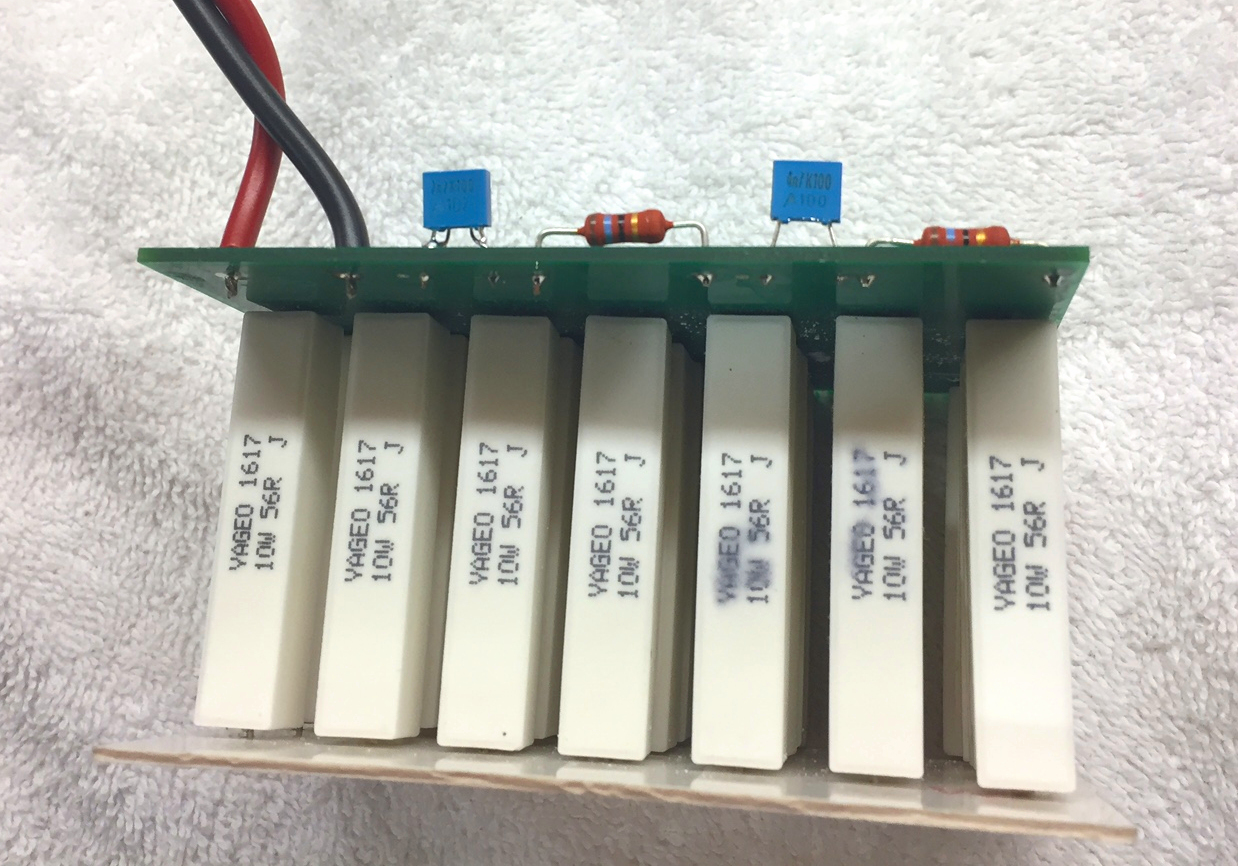
I used twenty eight resistors, each one 56R and 10W. Cheap, wirewound, cement encased, resistors. (14 in parallel) series (14 in parallel)
Then I connected a frequency compensator in parallel with the 8R0 resistor, to cancel out the inductance of all those wirewound resistors.
Then I connected a frequency compensator in parallel with the 8R0 resistor, to cancel out the inductance of all those wirewound resistors.
Martin, good point. I was thinking about resistors that cool themselves, like the ones Mark uses, but at such high powers they are indeed likely to need a heatsink. They can then all be mounted close to each other on a huge or a water cooled common heatsink.
I used twenty eight resistors, each one 56R and 10W. Cheap, wirewound, cement encased, resistors. (14 in parallel) series (14 in parallel)
Then I connected a frequency compensator in parallel with the 8R0 resistor, to cancel out the inductance of all those wirewound resistors.
This needs a 'like'. Very economic, and efficient, solution.
oh snap, another variable!
I imagine the resistors am using are wire wound as well.
I do have a cheap component tester that can "measure" (is a tester lol) Henrys (i have no idea of this unit / or scales)
I'll give measuring the resistor inductance using that tester a try. Am sure would be a quick google search but if you know off hand what value of inductance would be concerning?
Also am "not at all" educated / experienced with electricity; what is the consequence of my dummy load having some level of induction? Is that not going to be just additional form of power dispersion / work?
Which I suppose if it's significant enough and not accounted for would spoil calculations I do for power dissipated and by deduction power produced by the amp.
Is that the issue of inductance in the dummy load. Fearing the issue maybe possible damage to the amp.
(neat in that once I understand the issue of inductance here, it may help understand the frequency filtering they do...perhaps that is the issue of inductance in the dummy load, though cannot figure what / why / how)
preemtive strike! Is there a concern for capacitance of the dummy load? (i don't know if it's possible for a circuit of resistors to have a capacitance)
Last edited:
I'm going to be pragmatic here:
If your layout is reasonably tight, since you say these will be fixed to an aluminium heatsink; then the stray inductance is going to be small - likely no worse that that contributed by the layout of a crossover in a loudspeaker (approx similar loop -area) that your amp will drive!
If you have a means of measuring small values of inductance - say under 10uH maybe -then you will be able to compensate as nice as you like. Do have a read of the first few posts in the thread Mark Johnson linked above.
For my own pictured earlier -its a non-inductive wound part about 50mm long, it might contribute up to 1uH with leads attached* -and at that level, I really don't care for the things it is used for.
* 1 m of wire in free space is about 1uH, ballpark; say 50cm/18" of wire (x2 - there and back.). That figure drops by a factor of 10 or more once you are using a closely-bound pair, like speaker wire, or a twisted-pair of cables as I'd usually use. It is the loop area the circuit describes as a 'round trip' that dominates - above and beyond, what each load resistor contributes.
(In comparison with the above - stray capacitance effects are going to be significantly smaller still, and so rather less significant in effect on measurement of amp square wave response - which is the primary reason to think about dummy load inductance, as Mark's example)
Last edited:
Thank you for the detailed reply!
I will have a read of what Mark had linked; sorry I hadn't yet and thank you Mark for providing!
Another question popping up; you mentioned using square waves. How come? I feel like with sine it's more inline "real world" and at least for my simply understanding much easier to see clipping / interpreting what am seeing.
Maybe am not thinking of proper square wave frequencies, but wouldn't square waves use up headroom from power supply capacitors much differently than a sine wave? I envision the long peaks of square waves being an "unrealistic" test of the amp's ability to amplify a sound wave counterpart (the electric version of the sound wave lol)
I feel like a square wave would be testing the "absolute" continuous power output of the amp. That said it does seem like the frequency used if using square waves is much more important for interpreting the results.
That said, using a square wave, should show at least some time delay of voltage swinging the other way (i.e. not a perfect 90 square wave); I believe that is called "slew rate".
so "messy" learning without a curriculum lol but huge thanks to all responding, is valued for sure!
That said, very often max power is tested at 1khz; and of course that would be ear bleeding frequency at max power; for "real world" is likely 20-200hz range that really eats up the power when listening to some cranked Bach lol
But since that measure of max power is rarely (never?) done at 20-200hz range it must not matter the frequency being amplified; it can amplify any electrical signal (dependent on transistor speed) and in turn doesn't matter the type of wave or frequency...power is power.
But am still hung up the difference in "roll up to" and duration of peak to peak between square waves and sine waves and the impact that (may?) have on headroom. (if I understand right the charge in the power supply capacitors would not have a change to "fill up" and provide power needed for the short peaks of a sine wave when the amp is pushed to such limits.
Last edited:
We all learn, hopefully all the time - sharing what we come across is wholly positive; heaven knows I've been helped by others in turn over the years, and in as much as I have been given freely... it is good to share!
Anyway:
Rod Elliott's excellent website has an article as to why using square waves in measurement is informative; HTH:
Squarewave Testing
Anyway:
Rod Elliott's excellent website has an article as to why using square waves in measurement is informative; HTH:
Squarewave Testing
Last edited:
- Home
- Amplifiers
- Solid State
- Making a resistor bank to dump amplifier output into