I have a Luxman LV -117 which had a bad protection relay. I got an appropriate replacement, it should be 9v on the coil. For some reason I am getting around 30von both side of the coil and the relay is not switching. Im not sure why. I have checked and replaced the protection ic 1360 and weveral of the diodes in the subcircuit. I cant figure out how im getting excess voltage there. Here is a snapshot of the section I think should cover it. All the other voltages in the amp seem to be normal. Any ideas?

Do you see 30V on both sides of R6402 and at pin 6 of IC6401 ? If so, IC6401 must not be powering the relay; so then try shorting pin 6 of of the IC to ground to confirm that the coil will energize the relay. If the relay closes with the short, let us know and we'll troubleshoot the protection IC.
Good luck! Merry Christmas!
Good luck! Merry Christmas!
30V on both sides of the coil indicates no current flow, ie, order to operate the relay from IC has not been received (Pin 6 as per BSST).
Because no current flow there will be no I x R volt drop so certainly expect voltage above 9V, though 30V does sound to high, relay typically draws 40-50mA.
Looking further relay power appears to come from IC1503 (NJM7809) so 30Vdc at relay coil indicates a dead NJM7809 along with surrounding caps and...
Remeasure Vdc at relay diode cathode and any black speaker connector.

With pin 6 shorted to ground, take voltage measurements on both sides of R6402 and the relay coil to determine where voltage is being dropped.
If most voltage is dropped across the resistor, its value may have increased dramatically.
If most voltage is dropped across the resistor, its value may have increased dramatically.
With +30Vdc "from" IC1503 I'd be a little concerned about doing damage to the relay coil. Maybe a basic health check of psu, ie, verify that it is a 9V regulator and no failure/short between IN/OUT legs. Can't see where the 30Vdc is coming from, schematic shows regulator fed from 10Vac winding.
Apologies, I meant use the black connector as GND, the 30Vdc is totally wrong, thought it was a measurement error with grounding maybe???No dc on black speaker connections.
mbz comments prompted me to actually find and download a service manual.
30V at the relay is very unexpected, as the relay is powered from a 7809 regulator, so +9V would be the expected voltage at the relay coil. Even if the 7809 regulator were shorted, the unregulated supply voltage shouldn't be 30V--- more like ~12VDC. Investigate the regulator and the regulator ground connection to the rest of the ground network.
I'd do this first: confirm continuity from IC6401 pin 5 to chassis ground. (I suspect with a missing IC6401 ground connection, protection sensing signals may "back feed" into the relay drive and cause the peculiar 30V. This could also explain no drive to relay coil.)
Last edited:
Thank you all for your help. I am tracking down these suggestions. Working on troubleshooting the supply regulators. May need to order some. Ill update ASAP.
IC6401 does connect to ground. I replaced the 7809 reg with a 7812 (didnt have 9v) but I now get 11v approx. But my voltage is still not appearing on ic6401 correctly. Checking the IC orientation. Voltage is dropping from 38vdc to 3vdc across r6404 going toward the ic6401
Last edited:
11V seems reasonable, as the unregulated supply probably doesn't have enough headroom to deliver the full 12V at the regulator output. Is relay coil voltage now 11v? Again, try shorting IC pin 6 to ground to test for relay closure. An easy test.
If I understand correctly, you now have 11Vdc at relay diode cathode (D6401).
Now the problem is R6404 (38V to 3Vdc),
Schematic shows ZD6401 (20V zener) cathode to be at +58V so +38V expected at R6404.
EDIT Vcc is 25-60V so 3V is too low, suggests excessive current draw, check C6402 (100uf/16) possibly leaking to GND???
Now the problem is R6404 (38V to 3Vdc),
Schematic shows ZD6401 (20V zener) cathode to be at +58V so +38V expected at R6404.
EDIT Vcc is 25-60V so 3V is too low, suggests excessive current draw, check C6402 (100uf/16) possibly leaking to GND???
Last edited:
Yes. I had replaced c6402. Double checked its connections. I could replace it again. I used a 35v 100uf axial.but should work Other possibilities?
High current flow through R6404 due to,Other possibilities?
- internal failure of IC6401, eg, low impedance path from Vcc pin to GND
- solder bridge or similiar on trackwork between R6404 and IC6401 Vcc pin
Measure resistance between "3Vdc side" of R6404 and any black speaker connector (ie, black meter probe connected to spkr connector)
Last edited:
What I have found so far..I get 10k to speaker gorund from IC side of R6404(3V) . I was uncertain of orientation of IC6401. So ive tried both ways and when I had pulled it I checked voltages and get 38vdc on both sides of R6404. It seems to definitely be something internal. N matter which way I orient the chip I get the voltage drop only when installed. I am suspicious of these chips . I bought a pack of 5 from china on amazon. I cant seem to find a great pinout layout description for the PC1237H. These are the linear one inline package IC's.
Does not sound unreasonable.I get 10k to speaker gorund from IC side of R6404(3V) .
The IC has a bevel edge on the top indicating pin #1I was uncertain of orientation of IC6401.
By doing so you may have damaged the ICSo ive tried both ways
People will ignore you if you continue to do such things. Troubleshoot based on measurement and theory, not on wims...
Yes, almost certainly fakes.I am suspicious of these chips . I bought a pack of 5 from china on amazon
Suggest remove the current IC and mark it suspect faulty (due to insertion with incorrect orientation)
If you have the original IC then insert that or clearly explain why it's faulty, in which case insert another on the amazon items.
I was expecting something like, where bevel on the end indicates pin 1.
The other type, as you correctly describe,
The other type, as you correctly describe,
do you mean the beveled edge faces you and pin 1 is on the far left?
Attachments

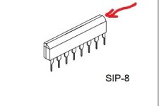
Based upon the data sheet I found, pin 1 is at the left side in both both pics. I.E. NOT near the red arrow in the second pic.
If you're removing the IC, and since its quality is unknown, I recommend leaving it absent for some voltage checks without the uncertainties its presence would introduce.
Then you can confirm +9V (11 due 7812 sub?) at the relay coil. Do a temporary short between the pin 5 and pin 6 pads; this should exercise the PC traces connecting the IC, and the relay should close. Test the voltages that show at the IC sense input pins to make sure that they are reasonable given the absent IC.
If all is well, then try installing fresh IC from the Amazon batch.
Good luck!
Attachments
Yeah my bad, red arrow was meant to indicate the bevel but... not well thought out, thanks for picking it up, apologies for any confusion.pin 1 is at the left side in both both pics. I.E. NOT near the red arrow in the second pic.
With IC6401 pulled(removed). Testing traces where its pins would connect , I get on pin 1 9.6v, pin 2 1.2v, pin 3 0, pin 4 58v, pin 5 0v, pin 6 0v, pin 7 37v, pin 8 38.4v. I get 0v to the relay coil as well.
- Home
- Amplifiers
- Solid State
- Luxman LV-117 Trouble with protection Relay