I have one non-working Luxman D225 CD Player, which have dead laser. Can anyone help me with info about optical pick-up type on this model? Schematic will be even better.
Thanks,
Chicco
Thanks,
Chicco
I don't have camera, but i will try to find a friend who has and i will post a picture.
Anyone have info of this Luxman CDP, or i'm the only one with this player?
All the best,
Chicco
Anyone have info of this Luxman CDP, or i'm the only one with this player?
All the best,
Chicco
Hi Chico,
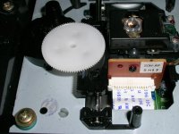
The part number on the laser head is SOH-AP. Make sure the cable is good (or be careful when changing the head).
Why do you think the head is bad? It's the most common misdiagnoses.
-Chris
The part number on the laser head is SOH-AP. Make sure the cable is good (or be careful when changing the head).
Why do you think the head is bad? It's the most common misdiagnoses.
-Chris
Hi Chris,
I'm not shure at all, but everiting seems to work ok, logic, motors, sensor switches...
This is Samsung head i gess, not fammiliar with it.
I didn't have schematic, so it's hard to examine everiting and to be 100% shure.
I will apriciate every help,
thanks to all!
Chicco
I'm not shure at all, but everiting seems to work ok, logic, motors, sensor switches...
This is Samsung head i gess, not fammiliar with it.
I didn't have schematic, so it's hard to examine everiting and to be 100% shure.
I will apriciate every help,
thanks to all!
Chicco
Hi Chris,
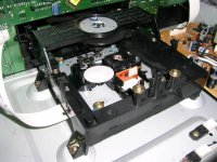
When the disc is in, spindle motor rotates the disc and laser tries to read it without success for a couple of minutes. With empty tray there is red light from the laser head, and if disk is not inserted, “no disk” command on display shows up. So, I guess logic is ok, but laser is too weak to read the disc content properly.
Chicco
P.S.: I can borrow from a friend an old Philips 10 Mhz oscilloscope if is worth at all.
Borrow the Philips, much better than nothing.
I will look into the archives and get back to you tomorrow.
-Chris
I will look into the archives and get back to you tomorrow.
-Chris
Hi Chicco,
I don't have that one, sorry.
What I want you to do is put the probe on the RF test point. Settings are 0.5uS / div (or as high as you can go) and 0.5V/div. use a 10:1 probe. You will see an RF waveform called an "eye pattern". What you normally would do is adjust the focus bias for the highest amplitude and sharpest pattern. Do not move any control very much. The next adjustments can get you into trouble easily. They are tracking offset and E-F balance. Do not touch without the service manual.
Send a picture of the RF test point before you do anything. It can be hard to catch. Also, try to measure (DC volts, 2-10 V scale) across a normally 22 R resistor near the RF amp that goes to the flat cable for the pickup head. Calculate the current. Compare to the Iop figure normally printed on the head. I use a laser power meter for quick checks, but they are expensive and I don't know what the expected value is for that head.
-Chris
Hi Chris,
I spoke with my friend, he have hand made probe with 50 Ohm cable and termination on both ends of the cable with 50 Ohm resistors. Scope has 1Mohm/30pF input. Is it good at all?
In my first inspection I didn’t find adjusting pots, and without schematic I will have hard time to find measuring points and right values.
Thursday I will have more time to examine this problematic CDP and I will post new info.
Chicco
Hi Chicco,
Sadly, that probe is exactly what you do not want in this application. What is required is a low capacitance 10:1 probe. 10Mohm input impedance (DC). This is the most common probe supplied with an oscilloscope. Common specs are 50 MHz or 100MHz bandwidth for the probe. Really old probes were speced at 10 MHz.
To use an oscilloscope for servicing, this is what you need to get a hold of.
-Chris
- Status
- Not open for further replies.
- Home
- Source & Line
- Digital Source
- Luxman D-225 optical pick-up replacement