Trying to do a little THD simulation with LTSpice.
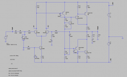
Simulating Rod Elliotts P3A I get huge input sine wave THD which ofcourse screws up the whole simulation.
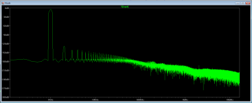
See attached pictures.
Did I overlook some obscure LTSpice setting?
Simulating Rod Elliotts P3A I get huge input sine wave THD which ofcourse screws up the whole simulation.
See attached pictures.
Did I overlook some obscure LTSpice setting?
Attachments

Last edited:
Your .four statement is incorrect. It doesn't understand "1-khz". Try ".four 1000 9 V(input)" or ".four 1k 9 V(input)".
It'll run faster if you set the max step size to say 1u. Usually, 1/1000th the period of the input is fine.
Bill
It'll run faster if you set the max step size to say 1u. Usually, 1/1000th the period of the input is fine.
Bill
It works now, great. 😀
Thanks alot for the help. 🙂
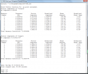
But as the picture shows, at 1kHz, 50W into 8 ohm load the THD is above 0.1%.
And at the same power into the same load but at 20kHz the THD is 1.3% 🙁
Would like to get atleast the 1kHz THD below 0.01 if possible and the 20kHz THD below 0.1
But now I can get started.🙂
Thanks alot for the help. 🙂
But as the picture shows, at 1kHz, 50W into 8 ohm load the THD is above 0.1%.
And at the same power into the same load but at 20kHz the THD is 1.3% 🙁
Would like to get atleast the 1kHz THD below 0.01 if possible and the 20kHz THD below 0.1
But now I can get started.🙂
Attachments
Last edited:
A good start would be setting the output stage idling current. The ratio of R7 to R9 looks wrong, IMO.
A good start would be setting the output stage idling current. The ratio of R7 to R9 looks wrong, IMO.
Indeed it is. It was just a start to get the simulation going. 🙂
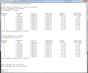
Well after reducing R7 to 450 Ohm, which gives an output stage idle current of about 60-65 mA THD-20 at 50 W into a 8 Ohm load is now down to 0.8%.
Better but not perfect, however the THD-1 should be a good deal better as well.
And indeed it is, THD-1 at 50 W into a 8 Ohm load is now down to 0.08%.
Better but not perfect, however the THD-1 should be a good deal better as well.
And indeed it is, THD-1 at 50 W into a 8 Ohm load is now down to 0.08%.
Last edited:
An interesting thing is that eventhough Rod Elliott advises to use between 20-100mA idle current for the output stage a simulation with even higher idle current shows a definate improvement.
250mA output stage idle current gets THD-20 numbers of around 0.65% at the same 50 W in to an 8 Ohm load.
Guess going higher than recommended is a good thing, as long as you have enough heatsinking.
250mA output stage idle current gets THD-20 numbers of around 0.65% at the same 50 W in to an 8 Ohm load.
Guess going higher than recommended is a good thing, as long as you have enough heatsinking.
Yes, in many cases, higher idle current will yield less distortion - until the peaks get to the top of the linear part of the transfer function (i.e. clipping), and then things get nasty real fast.
Bill
Bill
Self, Cordell's amplifier design books are a big help learning how to reduce distortions
currrent mirror load in the diff pair collectors equalizes diff pair current for less input stage distortion - the 1st step I'd take since increased loop gain is less useful if the diff pair can't accurately measure the error V to apply negative feedback
two more steps
"beta enhanced " VAS - a ef buffer between the diff pair out and the VAS Q with Cdom enclosing both
and a ef buffer btween the VAS out and the (compound) output Q - for a total of 3 Q giving current gain after the VAS
I have posted a Ltspice version of one of Bob Cordell's book's example circuits to explore stability/compensation in http://www.diyaudio.com/forums/soli...lls-power-amplifier-book-134.html#post2420438 (my stability example circuit derived from Bob's posted asc http://www.diyaudio.com/forums/solid-state/171159-bob-cordells-power-amplifier-book-119.html post 1184)
this uses all 3 tricks suggested but with straight "triple" ef/darlington output, just rearanging the last 2 output Q for your CFP and adjusting bias should be quick
Last edited:
- Status
- Not open for further replies.
- Home
- Design & Build
- Software Tools
- LTSpice way too high input sine wave THD