Well, here we are:
Left pic:
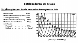
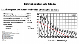
Operating data as a triode
13. Screen tied to plate, suppressor grounded
Heater voltage 12.6 V
Max. plate supply voltage 400 V
Max. plate voltage 800 V
Max. plate dissipation 40 W
Max. plate idle current 30 mA
µ = 20
gm = 2 mS
Right pic:
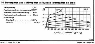
14. Control and screen grids connected (suppressor grounded)
Heater voltage 12.6 V
Max. plate supply voltage 1000 V
Max. plate dissipation 40 W
Max. plate idle current 30 mA
µ = 28,6
gm = 5 mS
Hope that helps!
Left pic:
Operating data as a triode
13. Screen tied to plate, suppressor grounded
Heater voltage 12.6 V
Max. plate supply voltage 400 V
Max. plate voltage 800 V
Max. plate dissipation 40 W
Max. plate idle current 30 mA
µ = 20
gm = 2 mS
Right pic:
14. Control and screen grids connected (suppressor grounded)
Heater voltage 12.6 V
Max. plate supply voltage 1000 V
Max. plate dissipation 40 W
Max. plate idle current 30 mA
µ = 28,6
gm = 5 mS
Hope that helps!

"Durchgriff" = (1/mu) x 100%
So 20% corresponds with mu = 5 and 0,35 % with mu = 285
Edit: I am not so sure about the max. idle current of 30 mA in triode mode. That value looks too low to me. But this value appears in more datahseets (EL152, FL152, P50) so it's a bit of a mistery to me.
Edit 2: I found this so the 30 mA must be wrong.
Attachments

I have no experience with LS-50, but GU-50's plate resistance in triode mode is about 800-900 Ohm
TG would you post your data here please....much appreciated.
Attachments
I believe they are for different specific use cases irregardless of same socket and pin out. That and the possible inclusion of a zirconium (high temp + self healing) getter with the standard barium getter.
GU-50 is technically the LS-50 clone, but copies aren't always equal to their prototypes indeedI believe they are for different specific use cases irregardless of same socket and pin out.
That's just wasting the tube 😀
Push-pull, 400V B+, 100mA per tube, Ra-a=6.6k - about 25-30 clean watts at the output (GU-50 is not very well suited for SE due to large 2nd harmonic)
Push-pull, 400V B+, 100mA per tube, Ra-a=6.6k - about 25-30 clean watts at the output (GU-50 is not very well suited for SE due to large 2nd harmonic)
Hi RajkoM.
Would you post your calculations here please....much appreciated.
Tube math is something I would like to learn!
Would you post your calculations here please....much appreciated.
Tube math is something I would like to learn!
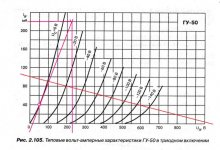
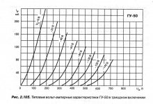
''Ua/Ia = 230V/220mA''
This is not arbitary.....how have you selected for these points on the curve?
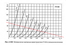
Also would you explain that line running from 50V to 230V.
Thanks for your patience
This is not arbitary.....how have you selected for these points on the curve?
Also would you explain that line running from 50V to 230V.
Thanks for your patience
- Home
- Amplifiers
- Tubes / Valves
- LS50.....GU50 Translation Please