I will be posting information about my new design balanced amplifier.
Today, the amplifier schematic, and a picture of the amplifier.
Soon, the power supply schematic, another picture, and my discussion of the design decisions I made.
Later, measurements of the amplifier performance.
Today, the amplifier schematic, and a picture of the amplifier.
Soon, the power supply schematic, another picture, and my discussion of the design decisions I made.
Later, measurements of the amplifier performance.
Attachments


I built a similar balance differential PP amp like this. I used a LM317-CCS for the first driver's cathode.
I am attaching my comments related to my designing and building these balanced monoblock amplifiers.
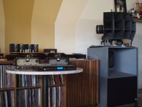
The amplifier received good comments when played at a local audio meeting.
Of course, having giant, heavy, very efficient loudspeakers, was a large part of the reason it sounded good.
Also attached is a picture of one of the loudspeaker systems, my two mono-blocks, and my balanced output CD player.
I still need to draw a power supply schematic; and list the amplifier measurements results.
Then hopefully someone will be inspired to design and build a high power balanced amplifier.
Attachments
Last edited:
It should have been spinning - lol
6A3-
Not to demean.. thx for your contrib's to this site. I read your posts and learn
Jim
6A3-
Not to demean.. thx for your contrib's to this site. I read your posts and learn
Jim
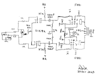
Very nice. Took me a minute to get your schematic. What are the 50k resistors wired to in the output stage?
There is a 50k resistor from each cathode. It goes to the meter.
The meter is just an indicator of the cathode voltages (and current, of course) that I can see anytime.
If an output tube was to go into thermal run-away, the meter would tell.
Or, if an output tube was to go weak or dead, the meter would tell.
Truth be told, I used meters when I started doing single ended outputs like 300B and 2A3.
When I converted those chassis to push pull or balanced, the single meter stayed.
Originally I used a switch to read one output tube at a time, but later got rid of the switch, and used 2 resistors to indicate the 'sum' of the voltages.
Ok so those little "Y" symbols represent the beam forming plates? Looked like they had a separate connection to the cathode but no. Clever use of a voltage meter as a system health monitor. And you get the sum of the cathode voltage, not the average?
dubadub,
You are really paying attention. Good!
Each output tube cathode has a 500 Ohm self bias resistor.
But the self bias resistors and cathodes are connected together through a 10 Ohm resistor, so a 1mA difference of cathode current causes 10mV across the 10 Ohm resistor (notice the test points that are connected to the 10 Ohm resistor). Measure the voltage difference, and calculate the current difference (which is also the current difference in the plate/screens, which also is the current difference in the output transformers primary halves).
Push Pull primaries do not like un-balanced current, saturation occurs early from the mis-matched current. I shoot for 500uA or less (5mV).
Y symbols = Beam Formers
dashes or circles = grids
The old tube schematic Base drawings showed the beam formers. That indicates a Beam Power tube.
Beam Formers are internally connected to the cathode (inside the glass envelope).
If instead, the tube was a pentode, I would have drawn a Suppressor Screen, and connected it to the cathode.
Most often for power pentodes, the suppressor screen is connected internally to the cathode (inside the glass envelope).
The EL34 and the 6CA7 are the only power pentodes I can think of that do not internally connect the suppressor grid to the cathode.
I am sure there are others, but you have to research that for yourself, I never used any other power pentodes that brought out the suppressor grid to the outside connection.
Instead, for the EL34 / 6CA7, the suppressor grid is tied to Pin 1 of the Octal Base (and the cathode is connected to Pin 8 of the Octal Base).
For 99% of applications of the EL34 and 6CA7, be sure to connect Pin 1 and Pin 8 together at the Octal Socket.
Do not let a suppressor float.
As to the meter, the two 500 Ohm resistors, the 10 Ohm joining resistor, and the two 50k resistors allow the meter to indicate the voltages of the two 500 Ohm resistors, which is according to the total cathode currents. Just imagine if one tube had no current.
Trust me, if one of the tubes goes bonkers, the meter needle will indicate a change from its normal position.
Last edited:
Thanks for sharing the content. Is this the symbol of the bim tetrode power tube? did you see anywhere this?
The Red Arrow is pointing to the Screen.
The beam former plates are positioned between the Screen, and the Plates. Looks like a Y or inverted Y.
Only connected one Y, the other Y is connected inside the tube (assumed, so no connection shown to eliminate just one more wire that would "get in the way" of the other drawing wires).
The screen is connected to the plate through 100 Ohms. The beam formers are connected to the cathode.
A pentode takes out the two Y-s, and instead, puts in a third grid, the suppressor grid, between the screen and the plate (3 more circles, I prefer to draw circles instead of dashes).
Just for fun . . . tube rollers often forget for the perfect comparison of pentodes and beam power tubes.
The EL34 pentode, and the KT77 beam power tube. They have almost identical electrical specs.
The EL34 pentode has a suppressor grid.
The KT77 beam power tube has beam formers.
Whether you are using the tubes in their native mode (pentode and beam power); Ultra Linear mode; or Triode Wired mode . . .
if the amplifier output tubes are self biased, you can easily interchange the EL34 and KT77 (there has to be a Jumper wire between Pin 1 and Pin 8). There are no other adjustments needed . . . Plug and Play.
Last edited:
6CA7 is beam-power, but same specs as EL34, ya?
Could one use your voltage -of-cathodes voltmeter circuit with a pair of single-ended tubes in the same fashion, or would that lead to cross talk between the channels?
Could one use your voltage -of-cathodes voltmeter circuit with a pair of single-ended tubes in the same fashion, or would that lead to cross talk between the channels?
A typical single ended stereo amplifier with each output tube self biased (an individual self bias resistor and a bypass cap across it for each tube) . . .
No crosstalk when you use a series resistor from each output tube to the meter; each self bias resistor voltage is as constant as the bypass cap can make it.
That is a nice idea, it only requires one current meter, 2 resistors to convert cathode voltages to current to the meter; and there is no switch required.
Simple, takes less space, less expensive (one meter, no switch).
Yes, 6CA7 and EL34 very close specifications.
6CA7, EL34, KT77, Just remember to jumper from Pin 1 to Pin 8 for the 6CA7 and EL34, the KT77 does not care, it ignores the jumper.
But if you want to compare pentode versus beam power, it is either 6CA7 and KT77; Or EL34 and KT77.
Last edited:
I was considering a 500v meter displaying b+ on my next build as a general status indicator but a measure at the cathodes is much more useful...
And it's always nice not to have to make 2 big holes in a steel chassis when one will do.
And it's always nice not to have to make 2 big holes in a steel chassis when one will do.
Oooh,
Oh no!
[magnetic] steel chassis will conduct magnetic fields from the power transformer, and from the filter choke . . . to the single ended air gapped output transformer.
Hum, Hmmmm.
Oh no!
[magnetic] steel chassis will conduct magnetic fields from the power transformer, and from the filter choke . . . to the single ended air gapped output transformer.
Hum, Hmmmm.
I've built 1 amp with aluminum top plate, 2 in Hammond steel chassis w black powdercoat, and a handful of Chi-Fi kit amps with folded stainless steel chassis with wood end caps. None of em display any hum. I don't have 103db speakers, my Polks are 90db, those Overnight Sensations, KRK 7000b (sound like crap with the 6B4G SET) but never hear any hum at all. I'm sure more sensitive speakers would reveal more, but I'm not hearing any hum. Even built Phono Pre in the steel chassis. I'm well aware of the conventional wisdom but my practical experience has led me to believe otherwise. Folly, I'm sure.
- Home
- Amplifiers
- Tubes / Valves
- Low Power Balanced Mono-Block Tube Amplifier