I'v decided to go down the open baffle/h-frame path (base on Martin J. King's work) but I'm having a great deal of trouble finding schematics for low gain SE tube amps. Reason being that I already have an F5 ( Voltage gain of 15db ) which i was hoping to use for the bass side of an active crossover. Anyone know of a SE tube amp with similar voltage gain?
Thanks
Dave
Thanks
Dave
Wow, that's an incredibly open question. Your F5 has a gain of 10, according to the schematic.
I'd start with Claus Byrith's SE output stage. Consider circuit 5 (page 9) that uses local cathode feedback. Use an EL34 or KT-88, single or in parallel for higher power (adjust voltages appropriately). For this exercise, only read Section 4 of Byrith's paper, which focuses on the output stage.
In this configuration (circuit 5, page 9) with EL34 at 375V B+, the output stage needs 2.85V drive for 1V output into 8 Ohms.
Consider the 6CG7/6SN7 (gain of 10) as the driver stage. The total gain will be 1V input -> 10V gain with 6CG7 -> EL34 output stage -> 3.5V into 8 Ohms (5 Watts). This isn't enough gain.
To match your F5, the driver stage needs a gain of 30. Example: 1V input -> 30V gain in driver stage -> EL34 output stage -> 10.5V output. The 12AU7 has enough gain, but you may want to buffer the gain tube from the output tube.
Use the Aikido for your driver stage. It provides a gain stage, buffered output, and noise cancellation. You can use anything for V1 from 12AU7 (gain of 8), 6CG7 (gain of 10), 6DJ8 (gain of 15), 12AT7 (gain of 30), 12AX7 (gain of 40). Using the Aikido buffers the gain tube, minimizing distortion.
Use the 12AT7 as V1 of the Aikido to provide the gain of 30. The EL84 output stage will divide this by 2.85, for a overall gain of 10.5 (you would need to be recalculate this for the KT-88).
The cathode feedback of Claus circuit 5 requires either Lundahl or Plitron (specialist range) transformers. To use normal transformers (Hammond, Edcor, One-Electron, Electra-Print, etc.) configure the output stage in triode mode or UL mode (i.e. Claus circuits 1 or 3). The driver need to provide less gain without cathode feedback. In UL mode, the output stage needs 1.3V to provide 1V of output into 8 Ohms.
Consider an Aikido using a 6DJ8 for V1 (gain of 15). 1V input -> 15V gain 6DJ8 -> EL34 output stage in UL mode -> 11.5V into 8 Ohms
Your best bet may be using the 12AU7 as V1 in the Aikido and adding a minimalistic amount of global feedback to stabilize the amp and tweak the gain. Global feedback is not bad, especially if you are minimalistic in your implementation. Read page 20 of Byrith's paper.
I can post a schematic with all these things, if you want. If I were to endeavor in this project, I'd make an Aikido/KT-88 in switchable triode/UL modes, using the pair of Hammond OPTs sitting unused on my workbench (unfortunately, no cathode feedback).
Last edited:
Hmmm,
Why exactly do you require low gain? If you have a level control on the active crossover and/or one on your amps you use that to match the output levels. For example, if your bass amp has a gain of 10 and your main amp a gain of 20, you would trim the input voltage of the main amp (or output of the active crossover) to 1/2 the voltage of the bass amp. for an input of 1 volt, you would then get 1 volt to the bass amp and 1/2 volt to the main amp. The output of both amps will then be 10 volts. Any changes on your master volume will keep this ratio intact, so both amps apparent volume will be the same.
Actually, instead of trimming for voltage, you would be best to use a sound pressure meter and trim for volume of the output drivers, as the efficiency of the drivers is likely to be different.
Cheers,
Chris
Additional comments:
(1) You stated the F5 has a gain of +15dB, which is 5.6V/V gain. The schematic shows a gain of 10V/V. Which is it? Either way, there's a solution to your problem. Lower gain is good, because you can use the 6CG7/6SN7 (gain of 10), which are excellent tubes!
(2) My bad, Plitron doesn't make a cathode feedback single-ended transformer. I have the Plitron specialist range cathode feedback for push-pull, but they don't make a SE version. The Lundahl version will still work.
(3) I like cathode feedback because it implements local feedback around one of the worst offenders in the amp - the OPT. Typically, the way the OPT is be included in the feedback loop is by using global feedback. Cathode feedback allows the OPT to be included locally.
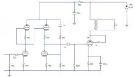
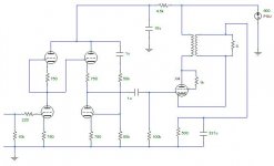
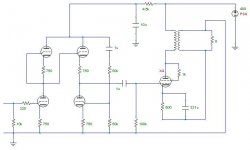
(4) D'oh! It is possible to use cathode feedback using ordinary transformers. Use the secondary itself as the cathode feedback. See circuits below. The first circuit is an Aikido driving an output tube connected in triode mode (no UL taps) with no global feedback. The second circuit uses the transformer's secondary as cathode feedback in the output stage (I may have the polarity wrong, but that's not the point). See how the output tube's current flows through the secondary? When output voltage appears on the secondary, it modifies the cathode's voltage, applying negative feedback. This means the secondary always has the bias current flowing through it, but it's very small compared to the secondary's capability (milliamps vs. amps). This current will generate a few mV across the secondary winding resistance. The third picture shows the cathode feedback with the secondary grounded. Don't pay attention to component values. I have no idea what I was simulating when I made these. Don't complain about the bypassed cathode resistor on the power tube. Use fixed bias if you want. It's just an example schematic.
(5) The Aikido has tons of local feedback. You can add local feedback to the output stage by configuring the output tube in triode mode. You can add more local feedback to the output stage by adding cathode feedback. Global feedback may not be necessary, although I'd incorporate some anyway. You can use a low-gain tube and leave local feedback disconnected, or use a high-gain tube and experiment with varying levels of global feedback.
(1) You stated the F5 has a gain of +15dB, which is 5.6V/V gain. The schematic shows a gain of 10V/V. Which is it? Either way, there's a solution to your problem. Lower gain is good, because you can use the 6CG7/6SN7 (gain of 10), which are excellent tubes!
(2) My bad, Plitron doesn't make a cathode feedback single-ended transformer. I have the Plitron specialist range cathode feedback for push-pull, but they don't make a SE version. The Lundahl version will still work.
(3) I like cathode feedback because it implements local feedback around one of the worst offenders in the amp - the OPT. Typically, the way the OPT is be included in the feedback loop is by using global feedback. Cathode feedback allows the OPT to be included locally.
(4) D'oh! It is possible to use cathode feedback using ordinary transformers. Use the secondary itself as the cathode feedback. See circuits below. The first circuit is an Aikido driving an output tube connected in triode mode (no UL taps) with no global feedback. The second circuit uses the transformer's secondary as cathode feedback in the output stage (I may have the polarity wrong, but that's not the point). See how the output tube's current flows through the secondary? When output voltage appears on the secondary, it modifies the cathode's voltage, applying negative feedback. This means the secondary always has the bias current flowing through it, but it's very small compared to the secondary's capability (milliamps vs. amps). This current will generate a few mV across the secondary winding resistance. The third picture shows the cathode feedback with the secondary grounded. Don't pay attention to component values. I have no idea what I was simulating when I made these. Don't complain about the bypassed cathode resistor on the power tube. Use fixed bias if you want. It's just an example schematic.
(5) The Aikido has tons of local feedback. You can add local feedback to the output stage by configuring the output tube in triode mode. You can add more local feedback to the output stage by adding cathode feedback. Global feedback may not be necessary, although I'd incorporate some anyway. You can use a low-gain tube and leave local feedback disconnected, or use a high-gain tube and experiment with varying levels of global feedback.
Attachments
Last edited:
I studied the F5 schematic over dinner, and the input stage FETs are configured for a gain of 10. However, the feedback loop consumes of the gain, for a total gain of around 5V/V (15dB). Of course, with most Pass designs, you can tinker with this as much as you want.
I have built a Zen v4, an Aikido/Zen hybrid, and an F4. Hellllooooo, F5!
I have built a Zen v4, an Aikido/Zen hybrid, and an F4. Hellllooooo, F5!
Thanks for the replies 🙂 Definitely some food for thought Kashmire. Didn't even consider using an aikido to drive a kt88. I'm using one as a line/headphone amp right now, and was going to use it as the pre for the active crossover. And your right Chris, it would make sense to just trim a pot at the input of the mid/high amp, but i thought it would be nice to have the two amps matched in gain, even though it's not necessary. Well, at least this project is going to force me to learn a lot more about tubes 🙂
I would make sure you sweat the important stuff, like making sure that the topology, power, layout etc are appropriate to your needs. Whatever the gain of the amp, you are going to require a method to adjust the levels (I would be surprised if the active cossover did have this adjustment) or it will not sound right. IMHO worrying about matching gain is not really all that relevant at all.
Cheers,
Chris
Cheers,
Chris
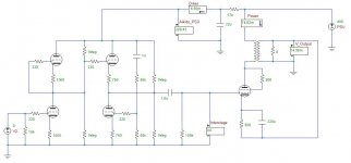
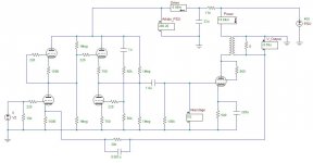
Attached is Aikido/KT88:
- Singled ended
- Triode output stage (can also be configured UL)
- Aikido gain/driver
- Ouput stage cathode feedback
With a 4800 Ohm to 8 Ohm transformer (impedance ratio of 600) and 400V B+ at 75mA, the KT88 can output +/-13V peak into 8 Ohms. Bigger impedance ratios will give higher output power, but also bigger (more expensive) iron. Attached schematics show everything, including safety resistors and grid stoppers.
With 12AX7 as V1 and no cathode feedback, the gain is 9.6V/V. Cathode feedback lowers the total gain to 7.4V/V. That's very minimalistic local feedback encompassing the KT88 and OPT. Excellent!
You'll get a little more gain with UL instead of triode mode.
Since the Aikido doesn't invert the phase, it's hard to implement an elegant global feedback along with the cathode feedback. It's one or the other. See schematic. Notice the OPT secondary is reversed. With the 20k global feedback resistor, the gain with a 12AX7 is 6.4V/V.
If I had to choose between local cathode feedback vs. global feedback, I think I'd choose the local cathode feedback. However, this is pure conjecture. The benefits of global feedback is the loop would encompass the gain tube (V1, 12AX7) and the coupling capacitor, along with the rest of the amp.
I'm now thinking about purchasing some SE OPTs to build this. I already have an extra set of Aikido boards, some 6CG7s, a bunch of KT88, and a Hammond 270HX power transformer. I can put together this amp in a single evening with my workbench parts, if I only had some SE OPTs ... and I can decide for myself by actual experience if global or local feedback will rule this day.
As per the gain arguments, I target most of my amps for around 10V/V. This seems to work well for me, because I can directly connect an M-Audio USB DAC, Musical Fidelity DAC, or an iPod without fussing with preamps.
Attachments
Last edited:
- Status
- Not open for further replies.
- Home
- Amplifiers
- Tubes / Valves
- Low gain tube amp?