This jitter measurement does focus on jitter on clocks and PWM signals of 200kHz-1MHz as widely used in class D amps.
The measurement does display the noise that is generated in the audio band by the jitter of a clock or PWM or level shifter or gate driver... .
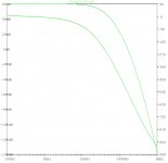
Basically the circuit is a high order filter with 60db gain over the audio band.
A 400kHz carrier is suppressed by 118db.
The equivalent input noise is approx 5uVrms, which means a measurement limitation of -117db, when considering a +/-5V PWM signal.
When checking a 400kHz PWM in time domain this would demand measurement equipment with an accuracy better than +/- 2ps.
In real life I am using two NE5534 (compensated with 39pF) for the voltage followers. The gain stage is working fine with LT1037.
At each OP amp there is a 100nF ceramic between pos and neg supply - not shown in the schematic.
The GND wiring should follow the geometric sequence as visible in the schematic. Suppressing 400kHz with 118db demands a certain discipline 😉
The -3db bandwidth is slightly above 17kHz, fitting well to simulation.
The measurement does display the noise that is generated in the audio band by the jitter of a clock or PWM or level shifter or gate driver... .
Basically the circuit is a high order filter with 60db gain over the audio band.
A 400kHz carrier is suppressed by 118db.
The equivalent input noise is approx 5uVrms, which means a measurement limitation of -117db, when considering a +/-5V PWM signal.
When checking a 400kHz PWM in time domain this would demand measurement equipment with an accuracy better than +/- 2ps.
In real life I am using two NE5534 (compensated with 39pF) for the voltage followers. The gain stage is working fine with LT1037.
At each OP amp there is a 100nF ceramic between pos and neg supply - not shown in the schematic.
The GND wiring should follow the geometric sequence as visible in the schematic. Suppressing 400kHz with 118db demands a certain discipline 😉
The -3db bandwidth is slightly above 17kHz, fitting well to simulation.
Attachments

first measurements
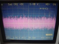
When the input is shorted we can find an output noise of approx 30mVpp.
Means 5mVrms, means an equivalent input noise of 5uVrms.
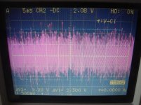
The second measurement is the noise of a standard signal generator delivering a 4.8Vpp rectangular with 400kHz. It has noise of approx 383uVrms in the audio band. Not fortunate as a source to generate a triangle! Assume we go for a +/-200mV triangle by a simple RC..., then the related RC will let pass the noise in the audio band in full. Means we have 383uVrms noise on the triangle. The triangle is being compared with an audio signal of +/-200mVpp... assume sinusodial.. means 141mVrms. 383uV noise on 141mV signal means -51db.
Even when considering that this poor value might be cured by the feedback loop, say the amp output might be 20db-30db better.. ..obviously it is making sense to spend some love on a low noise triangle for a clocked class D amp....
When the input is shorted we can find an output noise of approx 30mVpp.
Means 5mVrms, means an equivalent input noise of 5uVrms.
The second measurement is the noise of a standard signal generator delivering a 4.8Vpp rectangular with 400kHz. It has noise of approx 383uVrms in the audio band. Not fortunate as a source to generate a triangle! Assume we go for a +/-200mV triangle by a simple RC..., then the related RC will let pass the noise in the audio band in full. Means we have 383uVrms noise on the triangle. The triangle is being compared with an audio signal of +/-200mVpp... assume sinusodial.. means 141mVrms. 383uV noise on 141mV signal means -51db.
Even when considering that this poor value might be cured by the feedback loop, say the amp output might be 20db-30db better.. ..obviously it is making sense to spend some love on a low noise triangle for a clocked class D amp....
Attachments
Choco,...spend some love on a low noise triangle for a clocked class D amp....
this confirms a suspicion that I had for a while, namely that triangle generators seen in clocked designs are rather underwhelming for the most part. I just never got around to scratching my head on it and figure it out...

Thanks
-E
While layouting my new class D, I came to the conclusion that I should have a look to this before routing the oscillator...
In fact up to now I am not convinced that a crystal with frequency divider is necessarily better than an analogue hysteresis oscillator.
Right now measured the 310kHz/4.8Vpp analogue hysteresis oscillator (with low noise rail supply and LT1711) that I used some years ago to clock my MosFet relay. Finding 18uVrms. This means in time domain a jitter below +/-17ps (rms weighted), max. values +/-51ps. I never digged into the crystal oscillators and frequency dividers, but I am not convinced that you easily get such low jitter after dividing down to few hundreds of kHz.
Real life experiences and measurements highly welcome.
While layouting my new class D, I came to the conclusion that I should have a look to this before routing the oscillator...
In fact up to now I am not convinced that a crystal with frequency divider is necessarily better than an analogue hysteresis oscillator.
Right now measured the 310kHz/4.8Vpp analogue hysteresis oscillator (with low noise rail supply and LT1711) that I used some years ago to clock my MosFet relay. Finding 18uVrms. This means in time domain a jitter below +/-17ps (rms weighted), max. values +/-51ps. I never digged into the crystal oscillators and frequency dividers, but I am not convinced that you easily get such low jitter after dividing down to few hundreds of kHz.
Real life experiences and measurements highly welcome.
Hi ChocoHolic,
You can show triangle wave on oscilloscope with right zoom possible?
regards
Which zoom would be right from your view for a 400kHz triangle with +/-200mV?
Just let me know your desired time scale and voltage scale.
Just let me know your desired time scale and voltage scale.
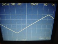
...something like this?
Thanks Choco, it is good to see the corner, I see that it is clean.
geometry also looks good, it is preferable to see at 400nS/Div.
have no doubt, which is much better oscillator with hysteresis for noise. a problem can be the amplitude of the triangular, is too low 200mV.
Regards
Measurements
..and now - why I build this measurement tool.... Measurements !
Measurements on analog hysteresis oscillators:
All Oscillators operated in the frequency range 310kHz-700kHz.
Bandwidth of noise measurement: 17kHz
1) Hysteresis Oscillator build from LT1711:
Output signal: 4.8Vpp ==> equivalent PWM audio signal: 1.7Vrms
Output noise: 18uVrms
S/N ratio: 99.5 db
2) Hysteresis Oscillator build from LM360:
Output signal: 5.6Vpp ==> equivalent PWM audio signal: 1.98Vrms
Output noise: 17uVrms
S/N ratio: 101db
3) Traditional astable multivibrator build from two BC550C:
Output signal: 9Vpp ==> equivalent PWM audio signal: 3.19Vrms
Output noise: 5uVrms
S/N ratio: 116 db
Noise measurements on triangle PWM modulators:
Approx +/-270mV / 312kHz triangle was derived from the second oscillator above.
RC of 1k8 and 4n7 directly at the input of the following comparator.
This triangle was connected to a comparator input, while the second comparator would be fed by the audio signal. For the noise measurement the audio signal was zero (jumper to GND).
The measured noise on the triangle was 11uVrms ==> S/N ratio of triangle: 85db
Findings on LT1711
Output swing 9.6Vpp
Output noise: 7mVrms !!! ==> S/N ratio of PWM: 54db
It was found that the noise could be massively influenced by the wiring of rectangle.
Another massive impact was found by putting a probe at the triangle ==> 2 times worse.
Looks like LT1711 has an unpleasant mechanism to transform HF-noise into a LF-jitter in the audible frequency range.
Note, the LT1711 did not show panically output flipping, also no obvoius jitter on scope screen.
Findings on LM360
Output swing 4.2Vpp
Output noise: 78uVrms ==> S/N ratio of PWM: 85db
Hi Dimitri,
...no, I did not measure the spectrum - but it should be possible to do so with a normal sound card and the RMAA software.
Instead of catching the noise spectrum, I simply listened to it.
There were differences, but less spectacular than the differences in intensity.
Feel free to dig deeper 😉
...no, I did not measure the spectrum - but it should be possible to do so with a normal sound card and the RMAA software.
Instead of catching the noise spectrum, I simply listened to it.
There were differences, but less spectacular than the differences in intensity.
Feel free to dig deeper 😉
- Status
- Not open for further replies.
- Home
- Amplifiers
- Class D
- low cost jitter measurement -117db