It seems there are several sharp cutoff pentodes specifically designed for relatively low B+ such as 6AK5,6J1P, 6J1. Seems like these might be very useful for powering straight off of an isolation transformer (120V mains). Anyone have a list of such? might be some potential $1 tube list candidates.
The usual old radio tubes like the 12AU6 and 12SJ7 work fine from rectified line voltage, but the 6 and 12 volt versions are still in demand, and supplies are dwindling, so they will never be on the dollar menu. However......
The last generation of TV IF amp tubes are all rated to 250, 300, or even 330 volts, but the characteristics for typical operation are all given at 125 volts......and 4 of them in multiple heater voltages are on the dollar menu, the 6JC6, 6JD6, 6KT6 and 6HM6. I have several of each and have successfully used all of them in audio amps. They all have high Gm so lead dress, ferrite beads and stopper resistors are your friends, especially when connecting these tubes directly to mosfets.
The last generation of TV IF amp tubes are all rated to 250, 300, or even 330 volts, but the characteristics for typical operation are all given at 125 volts......and 4 of them in multiple heater voltages are on the dollar menu, the 6JC6, 6JD6, 6KT6 and 6HM6. I have several of each and have successfully used all of them in audio amps. They all have high Gm so lead dress, ferrite beads and stopper resistors are your friends, especially when connecting these tubes directly to mosfets.
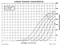
Good info. The gm curves seem to imply lower gm with reduced Vg2 which I presume would enhance stability at the expense of linearity at reasonable bias voltages.
Gm is largely a function of the current through the tube. The curves show Gm VS G1 voltage at several possible G2 voltages, Since both of these influence tube current, the curves represent their effects on Gm by of current control.
These tubes were intended for use as 45 MHz IF amplifiers in TV sets. Gain is controlled by modulating the current through the tube. Whether called remote, semi remote, "approaching semiremote" (RCA's words for the 6JD6), or sharp cutoff, the current through the tube will affect the Gm and at low currents, the linearity degrades due to the bunching of the curves. You will note the same characteristics in the 6AU6 and 6SJ7 curves, but we use them in audio amps. These tubes just have more room at the higher current end of the chart because of their fat cathodes and frame grids.
In audio use the distortion created is primarily second harmonic and will largely cancel in LTP or other balanced applications. A pair of these tubes in LTP can make a bunch of drive voltage at very low distortion if you bend the plate voltage spec a bit, OK, a lot. I run them at about 5 mA per tube, less when the plate voltage is over 400 volts.
The round object you see when looking at the tube is NOT the plate. It is the shield. The plate is the much smaller object inside the shield. I wouldn't go far beyond the dissipation spec. I haven't taken one of these tubes apart yet, but I will when I get a dead one.
As a kid tinkering with DIY guitar amps I found some unique sounding distortion could be had by swapping a 6SK7 (remote cutoff) into the 6SJ7 (sharp cutoff) socket on a Fender Champ clone then overdriving it. I didn't totally understand what I was doing then, but that didn't stop me from making amps.......and blowing them up.
https://frank.pocnet.net/sheets/127/6/6AK5.pdf
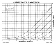
Seems a bit schizophrenic: the “absolute maximum” ratings for VA MAX < 180 V are violated in the transfer curve(s) at the bottom of the datasheet. VA MAX curves going all the way past 250 V.
Since the physical size of the 6AK5 isn't particularly tiny, nor since it seems to have specs that suggest it is internally an unusual tube as low power workhorse pentodes go, I don't imagine that flashover breakdown is a problem when using the 6AK5 at high anode potential.
But the PA MAX < 1.7 W rating is probably on the mark. Don't want to exceed that much. Well… obviously peak instantaneous dissipation can be much higher, but average should stay below PA MAX.
I wonder how a pair of 'em would do in a SRPP configuration. Seems perfect for B+ around 300 V in that service. Each tube only sees about ½B+. Inside VA MAX.
GoatGuy
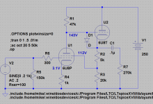
What I was contemplating is a topology akin to this but at a B+ of closer to 150V. Ref. Broskie

To get the gm down in the region of a 6N1P one needs to be around -0.75V g1 which is on the low end of reasonable for line inputs. This gives only 2mA Ia.

But the 6JC6A Vg1 v.s. Ia curves indicate that the linear region with 50V on g2 is about 0.3V g1 and 5.5mA Ia. Of course the circuit uses screen feedback so the over all result might not be horrible using the 0.75V bias point.

This is the trade-off I was referencing.

To get the gm down in the region of a 6N1P one needs to be around -0.75V g1 which is on the low end of reasonable for line inputs. This gives only 2mA Ia.

But the 6JC6A Vg1 v.s. Ia curves indicate that the linear region with 50V on g2 is about 0.3V g1 and 5.5mA Ia. Of course the circuit uses screen feedback so the over all result might not be horrible using the 0.75V bias point.

This is the trade-off I was referencing.
Last edited:
.... These tubes were intended for use as 45 MHz IF amplifiers in TV sets. ....
This piqued my curiosity, so I googled it, and came up with a totally off topic, but fascinating, account of development of a pentode for radar, operating at 6.7 meters ( about 45 MHz ):
The EF50, the tube that helped to win the War
Win W5JAG
Of course one could increase the feedback ratio and/or bias for a higher plate voltage on the Pentode since large voltage swing is not required.
Are you looking at driver tubes or power tubes? 6P15P and 6P43P can do some nice curves at lower voltages, and the 6P43P can make decent power too. If you hunt around you can manage $1-1.50 each for them too.
Are you looking at driver tubes or power tubes? 6P15P and 6P43P can do some nice curves at lower voltages, and the 6P43P can make decent power too. If you hunt around you can manage $1-1.50 each for them too.
In this instance driver and preamp applications but always good to have power options in mind. My 26E6 should do pretty well on rectified 120.
https://frank.pocnet.net/sheets/127/6/6AK5.pdf
...the “absolute maximum” ratings for VA MAX < 180 V are violated in the transfer curve(s) at the bottom of the datasheet. VA MAX curves going all the way past 250 V. ...
The curves only go to 240V?
The “absolute maximum” rating is a DC spec. With signal the plate voltage will swing below and *above* the idle point. The curves cover a 60V peak swing, which is kinda huge for IF and most RF use, but these tubes were used in transmitter "low"-level stages where a 60Vpk swing might happen.
Because arcs at <300V are rare, the 180V rating is probably about ion bombardment of cathode versus tube life. The dynamic swing has little effect because the life you lose on + swings is gained on - swings.
- Status
- Not open for further replies.
- Home
- Amplifiers
- Tubes / Valves
- low (120V) pentodes list