Hi,
As there are many people interested in loudspeaker protection circuit I made, I decided to place the project here.
Before I start, I want to let you know that there are other solutions such as discussed here:
http://www.diyaudio.com/forums/showthread.php?postid=1304013#post1304013
What I am writing about is just another implementation of the same thing.
Let's start with the schematics:
Attachments

Motivation. I respect my loudspeakers since I worked hard to get them and I want to keep them healthy as long as possible. Moreover, a protection circuit is a must in any amplifier. It solves a lot of problems which sooner or later appear in amplifiers. It is much better to burn a couple of cheap components, then to destroy expensive speakers, or even worse, to cause fire.
Theory. The basics of the circuit is DC detector, described here:
http://sound.westhost.com/project33.htm
It is a simple circuit which detects average DC voltage in a period of time. Parameters of the circuit can be altered depending on requirements. Inputs of this detector are signals from both speakers. They are rectified and smoothed into a DC voltage.
The second part of the circuit is an AC detector on the upper right of the schematics. Again, another simple sircuit, which detects a drop in AC voltage. It is used to turn off speaker relays when AC voltage turns off. It helps to avoid noise in speakers when powers turns off.
The third part of the circuit is a soft-start circuit which consists of four 5W resistors in series and a relay. When the power is turned on, the current of the primary coil runs through those resistors thus reducing the effect of core magnetization. Relay bypasses the resistors after 0.7-1 sec of time, leaving the primary of the transformer to operate in usual way.
On the right of the image are output relay drivers which are connecting the speakers to the amplifier.
Finally, the core of the device is PIC16F84 which drives all the logic and determines delays.
Practice. I was critised that I should have put optocouplers in transistors collectors in order to physically separate PIC from analog section of the amplifier. According to the critic, PIC can cause unwanted noise in output signal. Since it was too late for me to change the PCB, I took the risk and wired it all as is. Up to today, I have not heard any unwanted noise cause by PIC. However, I recommend to all to indeed use optocouplers for galvanic separation of the digital and analog sections. This is a practice in modern devices and there are strong reasons for doing it.
Parts used do not need to be expensive. They are all on a side of signal path and really they make insignificant interference to the quality of the output signal.
One detail should be wll thought of though, which is that 10uF capacitors in DC detector must not be bipolar. Otherwise they will explode due to potential inverse voltage which can be applied across their terminals.
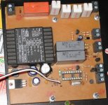
Finish. This is how the whole circuit looks:
Theory. The basics of the circuit is DC detector, described here:
http://sound.westhost.com/project33.htm
It is a simple circuit which detects average DC voltage in a period of time. Parameters of the circuit can be altered depending on requirements. Inputs of this detector are signals from both speakers. They are rectified and smoothed into a DC voltage.
The second part of the circuit is an AC detector on the upper right of the schematics. Again, another simple sircuit, which detects a drop in AC voltage. It is used to turn off speaker relays when AC voltage turns off. It helps to avoid noise in speakers when powers turns off.
The third part of the circuit is a soft-start circuit which consists of four 5W resistors in series and a relay. When the power is turned on, the current of the primary coil runs through those resistors thus reducing the effect of core magnetization. Relay bypasses the resistors after 0.7-1 sec of time, leaving the primary of the transformer to operate in usual way.
On the right of the image are output relay drivers which are connecting the speakers to the amplifier.
Finally, the core of the device is PIC16F84 which drives all the logic and determines delays.
Practice. I was critised that I should have put optocouplers in transistors collectors in order to physically separate PIC from analog section of the amplifier. According to the critic, PIC can cause unwanted noise in output signal. Since it was too late for me to change the PCB, I took the risk and wired it all as is. Up to today, I have not heard any unwanted noise cause by PIC. However, I recommend to all to indeed use optocouplers for galvanic separation of the digital and analog sections. This is a practice in modern devices and there are strong reasons for doing it.
Parts used do not need to be expensive. They are all on a side of signal path and really they make insignificant interference to the quality of the output signal.
One detail should be wll thought of though, which is that 10uF capacitors in DC detector must not be bipolar. Otherwise they will explode due to potential inverse voltage which can be applied across their terminals.
Finish. This is how the whole circuit looks:
Attachments
Documentation. I am providing SCH and PCB files for Protel 99. You do not have to follow them in details, it is enough to take them as a starting point.
Also, in the attachment you will find full source code for mikroPascal for PIC. Again, the code is very simple, and it can be easily ported to C, Basic, Assembly or whatever. It has no more than 60 lines of code and it is very easy to understand.
Please note that I will not take responsibility for any kind of damage you make by misusing these documents. Use them as a guide for your own development, completely at your own risk.
Attachments
Performance. I am very happy with this circuit. Firstly, it is very simple. It took me one afternoon to assemble it and to test it.
Secondly, program for PIC is very short. It solves a lots of headaches with various delays, logic etc. I wrote it in a moment of inspiration and I will keep it that way.
Finally, the protection is very fast. "AC off" detector is capable of detecting AC noise caused by vacuum cleaner. DC detection circuit is fast too, on ESP site it is said that it detects 5V DC in 20ms.
One improvement is recommended though, as I already said, try to use optocouplers to fully separate digital and analog grounds.
Recently I had a problem with one of the transitors in the amplifier. Actually, I do not know exactly what the problem was, but the outcome was that the insulation below the transistor did not do its job properly. Collector of the ouput transistor got short circuited to heatsink and therefore to chasis. Fortunately, the protection acted so fast that I did not hear any noise on the speakers, while the amp was sparking inside until the fuse went off. I think a better spontaneous test could not be done.
Secondly, program for PIC is very short. It solves a lots of headaches with various delays, logic etc. I wrote it in a moment of inspiration and I will keep it that way.
Finally, the protection is very fast. "AC off" detector is capable of detecting AC noise caused by vacuum cleaner. DC detection circuit is fast too, on ESP site it is said that it detects 5V DC in 20ms.
One improvement is recommended though, as I already said, try to use optocouplers to fully separate digital and analog grounds.
Recently I had a problem with one of the transitors in the amplifier. Actually, I do not know exactly what the problem was, but the outcome was that the insulation below the transistor did not do its job properly. Collector of the ouput transistor got short circuited to heatsink and therefore to chasis. Fortunately, the protection acted so fast that I did not hear any noise on the speakers, while the amp was sparking inside until the fuse went off.
I think a better spontaneous test could not be done.Vacuum Cleaner detector
zristic, forgot to mention the AC detect and triggering on vacuum cleaner switchon....
This sounds like a mini brown-out affecting the AC detect cct.
A suggestion would be to increase the value of R? (the resistor between base and ground on Q1)....try 2K2 or 4K7.
Increasing the voltage at the base should implrove riding out the brown-out.
You could put a small capacitor 100nf - 330nf to ground on the base of Q1 as well. This would hold the base voltage during any downward spike.
zristic said:
<snipped>
One detail should be wll thought of though, which is that 10uF capacitors in DC detector must not be bipolar. Otherwise they will explode due to potential inverse voltage which can be applied across their terminals.
Did you mean that the 10uF capacitors "must be bipolar" (rather than "must not be bipolar")?
- Tom Gootee
Bipolar capacitors
Interesting comment on use of bipolar capacitors.
As far as I was aware the bipolars were created mainly for crossover networks. Even Black Gate had a range of these for that purpose.
Many commercial speakers use bipolars in the crossover.
I woud agree that the "poly" and mica types would be better.
Would be interested in the reference to that info .....
Re: Bipolar capacitors
I would be surprised to learn that any basic type of passive electronic component was created specifically for any audio application. Bipolar electrolytic capacitors, and capacitors in general, are used in many orders-of-magnitude more non-audio applications than audio applications. As it is for most and maybe all mainstream passive electronic components, if they weren't broadly applicable in other types of equipment, we probably wouldn't even have them available just for audio, at least not with reasonable availability, pricing, and quality.
At any rate, bipolar electrolytic capacitors are usually just two polarized capacitors packaged together, in series, back to back. I often just use two polarized caps (each with twice the desired "bipolar" capacitance), instead, and sometimes put a large-value resistor in parallel with each one, to keep the voltages across them more equal.
And it is very well-known that significant reverse-biasing of a "regular" polarized aluminum or tantalum electrolytic capacitor is "a bad thing", and can result in an explosion. I don't have any references at hand. But you could probably find warnings on some of the capacitor manufacturers' websites.
muzza said:Interesting comment on use of bipolar capacitors.
As far as I was aware the bipolars were created mainly for crossover networks. Even Black Gate had a range of these for that purpose.
Many commercial speakers use bipolars in the crossover.
I woud agree that the "poly" and mica types would be better.
Would be interested in the reference to that info .....
I would be surprised to learn that any basic type of passive electronic component was created specifically for any audio application. Bipolar electrolytic capacitors, and capacitors in general, are used in many orders-of-magnitude more non-audio applications than audio applications. As it is for most and maybe all mainstream passive electronic components, if they weren't broadly applicable in other types of equipment, we probably wouldn't even have them available just for audio, at least not with reasonable availability, pricing, and quality.
At any rate, bipolar electrolytic capacitors are usually just two polarized capacitors packaged together, in series, back to back. I often just use two polarized caps (each with twice the desired "bipolar" capacitance), instead, and sometimes put a large-value resistor in parallel with each one, to keep the voltages across them more equal.
And it is very well-known that significant reverse-biasing of a "regular" polarized aluminum or tantalum electrolytic capacitor is "a bad thing", and can result in an explosion. I don't have any references at hand. But you could probably find warnings on some of the capacitor manufacturers' websites.
Bipolar capacitors
Gootee, thanks.
I did read somewhere a long, long time ago about bipolars and their development for use in crossovers... that just stuck in memory ever since.
I will do more investigation just to sate my own interest.
Yes, reverse biasing of normal polarised electrolytics does lead to interesting effects.
But this should not be an issue with bipolars as long as their rated voltage is not exceeded.
I have seen a bunch of examples where bipolar caps were used in crossovers in commercial designs.
I was more interested in zristics comment:-
"10uF capacitors in DC detector must not be bipolar. Otherwise they will explode due to potential inverse voltage which can be applied across their terminals."
That runs contrary to my understanding and experience.
Just wish to gain clarity of understanding.
Re: Bipolar capacitors
Sorry it is a typo, I meant they should be bipolar. As you can see on the image, I put bipolar MKT 10uF/100V. I apologize once again for the typo, I should not post after midnight...
My Sansui speakers originally had polarized caps in the crossover. I replaced them with bipolar caps. The only problem I've heard of concerning using unipolar caps in crossover was aging.
I, however, witnessed an explosion of a unipolar capacitor which was polarized reversely. In order to produce the effect you need to keep it runing reversely polarized sometime, which is rarely hapening in a crossover... Even if it happens, it is more likely that your speaker driver would die first, rather than a unipolar capacitor.
I was more interested in zristics comment:-
"10uF capacitors in DC detector must not be bipolar. Otherwise they will explode due to potential inverse voltage which can be applied across their terminals."
That runs contrary to my understanding and experience.
Just wish to gain clarity of understanding.
Sorry it is a typo, I meant they should be bipolar. As you can see on the image, I put bipolar MKT 10uF/100V. I apologize once again for the typo, I should not post after midnight...
My Sansui speakers originally had polarized caps in the crossover. I replaced them with bipolar caps. The only problem I've heard of concerning using unipolar caps in crossover was aging.
I, however, witnessed an explosion of a unipolar capacitor which was polarized reversely. In order to produce the effect you need to keep it runing reversely polarized sometime, which is rarely hapening in a crossover... Even if it happens, it is more likely that your speaker driver would die first, rather than a unipolar capacitor.
Bipolars
zristic... another night-owl 🙂
Thanks for that.... that matches my understanding wrt bipolars.
Best Regards.
zristic... another night-owl 🙂
Thanks for that.... that matches my understanding wrt bipolars.
Best Regards.
Hi zristic,
Thank you for posting this project. Personally, there is a lot for me to study in it. I normally design using hard wired logic and time constants.
I don't know if you really need that much isolation between your output circuit and protection logic. Most amps don't isolate these circuits, although digital based circuitry may be different. I guess it might depend on how much noise comes from the digital stuff. My first thought on this would be "not much".
I was talking to another member who sent me a link to your thread. He's from CircuitED.
-Chris
Thanks Chris.
I also wondered why such paranoia with separating digital and analog signals in simple projects like this. I believe that people face problems otherwise, therefore, I respected that advice and did the separation.
These days I am finishing another intereseting PIC audio project, hopefully I will publish it this weekend. It is an input selector with volume control, using analog optocouplers. There are threads on this subject all around the forum, just that my implementation is a bit different, thanks to PIC.
Warren is a cured audiophile, lucky him!
Hi zristic,
Well, I am very interested in your projects. I am about to attempt to teach myself the ways of PIC. 😉 I have purchased a PICKIT2 from Sure, and the emulator as well. I've also bought a TON of various PIC uPs and a couple books on the subject. My skills are in analog design and fabrication of prototypes. I have a very strong audio and telecommunications service background.
To be honest with you, I suspect many of our members would like to learn how to implement projects with what seems to be the easiest to use micro controller. One way to learn is to study examples. The other is to follow some kind of book based program. My biggest problem was I didn't understand what I needed to program and test these ICs with in order to learn. I originally wanted a programmer and bought an emulator. The descriptions are not clear for a newbie. To be honest with you, I'm still not 100% clear on what I need to do. I do think I have enough to start.
What we need is a guide to what we need that is also inexpensive (of course!), within reason. The people at Microchip seem eager to help also. I talked to a customer service representative about a month ago. Nice people.
There is another member (clem-o) that is skilled in programming. I'll bet you two could talk! It was very good of Warren to point me in your direction.
-Chris
Sansui ES-209 loudspeaker
I see you have a pair of Sansui ES-209 speaker. Are you interested in selling them? I'm sorry i can't contact you through email, but i'm still a newbie in this forum so i can't send you email
I see you have a pair of Sansui ES-209 speaker. Are you interested in selling them? I'm sorry i can't contact you through email, but i'm still a newbie in this forum so i can't send you email
Pragramming with PICs
Guys, there are three options wrt getting into programming:-
1. PICAXE.
This was created for the school environment. Uses a Basic language for the programming so is relatively easy to get into.
Great starter as the bits needed to program are very cheap e.g. the programmer is a cable and a few resistors.
Has an excellent De-bug function (via the same cable and few resistors).
Down side is that PICAXE chips are expensive.
Other limitations are a minor loss in flexibillity and that they run a bit "slow" as there is an onboard interpreter converting Picaxe Basic to machine code....not an issue dependant on the application.
See www.picaxe.co.uk
2. PIC Basic and Pic Basic Pro (Melabs)
Is the very best of the Basic for pics.
The compiler converts PB/PBP to a hex file and standard PICs can be programmed.
Same result, operationally, as working from Assembler (see option 3 below).
One needs a programmer unit to actually program the PIC.
De-bug is more complex as it is contingent on the programmer or Integrated Development Environment (IDE) used.
This easy to learn and use but expensive (US$250).
The MicroCodeStudio is an excellent IDE to use with this.
This is an excellent trade-off between PICAXE and Assember (see option 3 below) wrt ease of creating easy through to complex programs.
See www.microengineeringlabs.com
3. ASSEMBLER.
This is the hardest to learn and to use but is effectively FREE as the compiler and IDE are supplied by MicroChip.
One still needs a programmer unit. There are heaps of these on offer. Which one to buy depends on which PICs one will use as well as functionality of debug feature.
Finally- there are heaps of books on all three options available. The PICAXE docos are free to download. The books for the other cost $$$.
MYSELF - I started with PICAXE then graduated to Pic Basic Pro/Microcode Studio.
I still use PBP/MCS a lot of the time....due to ease and speed of development....my Protector/SoftStart board PIC was done in PBP.
I have also been, slowly, getting into Assembler and have done a few projects so far.
Hope that helps.
Re: Sansui ES-209 loudspeaker
@virtual3,
These are rare and very good loudspeakers, I am really happy with them. At the moment I see no reason for selling them. Thanks for the offer anyway.
@muzza,
I would not agree with you about the superiority of the tools you stated. Those are very old tools with serious limitations and I would not recommend anyone to use them. I would recommend beginners and other users to stick to real higher level languages. Simply, the learning curve with them is very steep. The tools you stated are very difficult to learn, not very efficient and finally, they are out of time. Todays microcontrollers have large program space and I am afraid that using assembly for programming them is just an utopia.
Finally, there is the risc that we turn my thread to non objective and never ending off topic discussion about programming languages, which would make me very unhappy. I suggest opening another thread for discussing the tools we (do not) like (I would not participate in it anyway).
virtual3 said:I see you have a pair of Sansui ES-209 speaker. Are you interested in selling them?
@virtual3,
These are rare and very good loudspeakers, I am really happy with them. At the moment I see no reason for selling them. Thanks for the offer anyway.
@muzza,
I would not agree with you about the superiority of the tools you stated. Those are very old tools with serious limitations and I would not recommend anyone to use them. I would recommend beginners and other users to stick to real higher level languages. Simply, the learning curve with them is very steep. The tools you stated are very difficult to learn, not very efficient and finally, they are out of time. Todays microcontrollers have large program space and I am afraid that using assembly for programming them is just an utopia.
Finally, there is the risc that we turn my thread to non objective and never ending off topic discussion about programming languages, which would make me very unhappy. I suggest opening another thread for discussing the tools we (do not) like (I would not participate in it anyway).
PIC tools
zristic, my last comment on your comments..... I also do not wish to enter into a debate....
I only offered the info as a place to start for the complete novice.
I did not use the word "superior".
The comparison was between several options.
At the bottom of the post you will see that it is based on my experience.
I did fail to advise there are several more wrt other languages.
I did try several of the other "Basics" and found that the PBP version was best...I maintain this opinion.
Yes, the PICAXE and PBP tools have been around for a while but are current products with PBP supporting all the latest PICs.
Depends what one wants to do with microcontrollers as to what language and what expense in compilers, debuggers, programmers.
In my case and experience (and I am just a hobbiest) I have built some 20 devices, some simple and some more complex (e.g. protocol converter). I have used Picaxe (early few projects) but mostly Basic via PBP and it has delivered a completely successful outcome each time.
Nuff said... topic closed on my side...
Hi zristic,
Thanks for sharing your work! Since you also shared the software part of your project at which i have no littlest cue, i thought of implemeting it directly without the hassle of understanding of the software part. I am also not familiar with Protel, so would you share a higher resolution view of the schematic in the first post if you still have it? I intend to transfer it to Eagle and if/when satisfied share it here.
First post done!..
Hello friend liked the project, could post the source code in C language and also the diagram in proteus or Jpg ? .....
Best regards,
Elias Novaes
Best regards,
Elias Novaes
- Status
- Not open for further replies.
- Home
- Amplifiers
- Solid State
- Loudspeaker Protector, my version