Hi All,
I have built a valve amp by copying an older one I'd built years ago, but this time I have used brand new up to date parts.
It has 2 EF86 for tone and volume, an ECC83 preamp and two EL34's as power valves, however, with the negative feedback connected I get an mighty loud, low frequency buzz from the speaker, but, with the loop disconnected I get a clean, but really quiet sound out of it. Even at full volume the output is about the same loudness as strumming an electric guitar that's not plugged in!
I have checked the circuit and rechecked it again and again and everything seems to match up with the original which works great with the feedback connected or disconnected.
Anybody any ideas as to where I might start?
thanks.
 Moved to Instruments and Amps
Hi All,
Anybody any ideas as to where I might start?
thanks.
Yes post the circuit then we can tell you where to test.
If you don't have the circuit post the output stage and driver/phase splitter.
Regards
M. Gregg
Thanks M,
will do - might take me a bit to draw it out. It's on an A3 sheet covered in notes at the minute, but I'll try sketch the relevant bits.
will do - might take me a bit to draw it out. It's on an A3 sheet covered in notes at the minute, but I'll try sketch the relevant bits.
Classic symptoms of the output transformer primaries backwards.
The push-pull output is out of phase so the NFB becomes PFB.
Reverse the primary leads, in other words take the two plate leads from the OT primary and swap sockets.
The push-pull output is out of phase so the NFB becomes PFB.
Reverse the primary leads, in other words take the two plate leads from the OT primary and swap sockets.
Reverse the primary leads, in other words take the two plate leads from the OT primary and swap sockets.
Thanks for the reply Enzo,
just to clarify. If I have the Green and Red going to 3 and 4 on the left valve socket, and Blue and Black to 3 and 4 on the right.
Do you mean change it to Green/Red on the right and blue/black on the left?
thanks.
When you show us the circuit I am sure we will find that the ECC83 is being used as a phase splitter (and possibly a voltage amplifier), not a preamp.JohnnyBoy23 said:an ECC83 preamp
Disconnect the feedback; get it working like this then put the feedback back.Anybody any ideas as to where I might start?
Check all DC voltages - in many cases this will be sufficient to highlight the problem.
Inject a signal at the output stage grid - does it come out at the output? Of course, use a loadspeaker or power resistor load so you don't damage the OPT.
If OK, inject a signal in the previous stage. Work back to the input.
Thanks for the reply Enzo,
Do you mean change it to Green/Red on the right and blue/black on the left?
Looks like that is what you meant. Have changed them around as above, reconnected the Feedback Loop and no huge wailing noise.
Thanks Enzo.
Still got the problem of the whole amp being really quiet though - even on full volume. I'll get on with drawing the circuit.
As the amp is loud when the global feedback is the wrong way round, it suggests that all the stages within that feedback loop are working OK. The problem causing the 'quiet' effect is probably in an earlier stage. (I was tempted to write 'must be' rather than 'probably' but I've learned over the years that electronics doesn't always behave the way I think it 'must' 🙂).
Thanks Malcolm, makes sense what you say. Maybe I'll start looking down the pre amp side of things first.
Cheers.
Cheers.
Thanks Malcolm, makes sense what you say. Maybe I'll start looking down the pre amp side of things first.
Cheers.
How is the output stage biased?
Regards
M. Gregg
Last edited:
When you show us the circuit....
Thanks DF96
still in the process of drawing it out - will work through your suggestions too and repost any results.
If the phase of the feedback is wrong, it will be positive feedback, which is guaranteed to oscillate at full volume, and possibly blow the speakers. If you cascade two EF86, there's a good chance that you have way more open loop gain than you want or need, which makes the phase margin issue more complicated.
Schematic
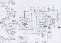
After about a gallon of tipex I've managed to draw the main part of the circuit - attached.
Also measured voltages and bias current - see diag.
NB. When I input a 1v signal - only 0.1v comes out of the Volume EF86 on pin 6 and then even less came from the tone controls into pin 9 on the other EF86 - I bypassed the tones by connecting the first EF86 pin 6 straight to pin 9 on the other. This produced a louder result, but still only just louder than the unplugged guitar. But at least it's in the right direction (maybe).
Would appreciate anyone having a look at the schematic and any suggestions made.
thanks,
John
Attachments
After about a gallon of tipex I've managed to draw the main part of the circuit - attached.
Also measured voltages and bias current - see diag.
NB. When I input a 1v signal - only 0.1v comes out of the Volume EF86 on pin 6 and then even less came from the tone controls into pin 9 on the other EF86 - I bypassed the tones by connecting the first EF86 pin 6 straight to pin 9 on the other. This produced a louder result, but still only just louder than the unplugged guitar. But at least it's in the right direction (maybe).
Would appreciate anyone having a look at the schematic and any suggestions made.
thanks,
John
Why,
Are there no resistors on pin5 of the el34? Ie pin 5 to ground!
Pin 5 on an EL34 is G1..input?
Just a first quick look..😀
Pin 9 is reliant on the wiper contact to ground the grid on the first EF86..perhaps 1 meg to Gnd pin 9.
Heaters on ECC83...in series? what voltage is the heater supply.. look here
https://www.google.co.uk/search?q=e...8DSQVS-GM:&usg=__hC-rMSj6MHt3WiW5U_nvnEdRs_c=
Is the supply across 4 and 5 or 4-5 and 9?
Pin 8 and 3 of ecc83 are cathode how is the cathode grounded?>>connected to pin 1 of the EF86 (grid)? or do you actually have the resistor on pin 3 to ground?
Just a few starters I can see others but..lets get some ideas on this..😀
Regards
M. Gregg
Last edited:
It’s an unusual circuit. Do you know where the original design came from?
The ECC83 seems to be a DC-coupled long tail pair phase inverter. The voltage on its two grids (pins 2 and 7) should be the same. However it’s generally impossible to measure grid voltages accurately – so that might be why you have 60V for pin 2 and 66V for pin 7.
The screen grid voltage (pin 1) of the ‘tone’ EF86 is directly supplied from the cathode voltage of the long tail pair (68V). Seems very unusual to me. I suppose the tail voltage is quite constant and so this could be a reasonable idea??? Or is there an error in the drawing?
On the ‘volume’ EF86, you are measuring a B+ of 305V and an anode voltage (pin 6) of 91V. You don’t give the value of the anode load resistor, but let’s guess it might be 120k. Which would mean an anode current of (305-91)/120 = 1.8mA for an EF86 with a screen voltage (pin 1) of 68V, an anode voltage of 91V and a cathode voltage (pin 3) of 1V. Assuming the grid is at 0V, these figures don’t seem unreasonable. So I am not sure why that EF86 seems not to be amplifying.
Simultaneous posting with M Gregg. Agree about the need for resistors to ground on pins 5 of the EL34s. Weird things would happen without those.
Last edited:
It’s an unusual circuit. Do you know where the original design came from?
This one looks very similar:
Linear Conchord 30 & L50 Schematic Diagram
I think I actually owned the 30 watt version when I was 18! 🙂
Why,
Are there no resistors on pin5 of the el34? Ie pin 5 to ground!
Pin 5 on an EL34 is G1..input?
Just a first quick look..😀
Pin 9 is reliant on the wiper contact to ground the grid on the first EF86..perhaps 1 meg to Gnd pin 9.
Heaters on ECC83...in series? what voltage is the heater supply.. look here
https://www.google.co.uk/search?q=ecc83+pinout&biw=1524&bih=710&tbm=isch&imgil=KKJgYzn0PY5NuM%253A%253B00HQIT-cNWgIlM%253Bhttp%25253A%25252F%25252Fwww.audiodesignguide.com%25252Fmy%25252Fel34_pse%25252Fel34pse2.html&source=iu&pf=m&fir=KKJgYzn0PY5NuM%253A%252C00HQIT-cNWgIlM%252C_&usg=__hC-rMSj6MHt3WiW5U_nvnEdRs_c%3D&ved=0CC0QyjdqFQoTCJm_n6a56sgCFca1FAodK9EKGw&ei=QIQzVpmfOcbrUquiq9gB#imgrc=8JLOD8DSQVS-GM%3A&usg=__hC-rMSj6MHt3WiW5U_nvnEdRs_c%3D
Is the supply across 4 and 5 or 4-5 and 9?
Pin 8 and 3 of ecc83 are cathode how is the cathode grounded?>>connected to pin 1 of the EF86 (grid)? or do you actually have the resistor on pin 3 to ground?
Just a few starters I can see others but..lets get some ideas on this..😀
Regards
M. Gregg
You're right there is a resistor on the EL34 from pin 5 to pin 6 to ground, my mistake.
On the Ecc83 pins 4 and 5 connected, so the heater is across 4-5 and 9. Heater voltage 5.7 v. Heaters in parallel.
Also, pin 3 is grounded through a resistor.
And you are correct Malcolm, as to the original, a Linear Concord 30.
I'll redraw the circuit more carefully, with corrections, and I'll put the resistor values on this time too. Where's the tipex gone?
thanks for your time on this M. and Malcolm too.
Grid Stoppers?
The Linear Conchord 30 schematic shows 2.2k grid stoppers on both EF86s and both EL34s.
Do you have those in your build? They are important for preventing ultrasonic oscillation, which just might be causing the problem. Grid stopper resistors should be soldered as close to the grid pin as possible.
There are also screen stoppers of 1k (1 watt) between the screens of the EL34s and the transformer UL taps. These are also quite important.
- Status
- Not open for further replies.
- Home
- Live Sound
- Instruments and Amps
- Loud buzz or clean but quiet.