Hi guys, I've decided to work on a car tube amp project and I'd like to use the Dynaco ST-70 as a 1st revision design. Considering how rare and expensive REAL commercial tube car amps are, I think this would be a great project and a good starting design.
The problem is, as I need to come up with my own power supplies, is that I don't have the voltage requirements listed anywhere, at least as far as I know. Also I don't have an amp to serve as a reference yet.
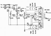
The ST70 manual has voltages listed at sockets and various other points in the amp, but not at the points shown in the attached pic:
If anyone knows what those are I'd really appreciate it.
Thanks.
The problem is, as I need to come up with my own power supplies, is that I don't have the voltage requirements listed anywhere, at least as far as I know. Also I don't have an amp to serve as a reference yet.
The ST70 manual has voltages listed at sockets and various other points in the amp, but not at the points shown in the attached pic:
- The negative voltage for the bias supply, (RD/BL wire) going to the bias circuit
- Voltages at numbered/circled points 1-4 in the power supply pic
If anyone knows what those are I'd really appreciate it.
Thanks.
Attachments
Last edited:
The ST70 manual has voltages listed at sockets and various other points in the amp,
but not at the points shown in the attached pic:
These will vary somewhat with the unit, tubes, and the line voltage.
Bias supply: -70VDC (after a silicon rectifier, replacing the selenium one), only 3mA needed.
HV supply (2, 1, 4, 3): +435/415/375/305.
Remember the AC filament supplies. Sounds like you won't need a 5VAC winding or rectifier tube.
Last edited:
Thanks a bunch!
Looks like I'm on track for starting with the DC-DC supplies I ordered (+450V, 75-600V adjustable).
I'll work on getting the -75V supply side figured out.
Looks like I'm on track for starting with the DC-DC supplies I ordered (+450V, 75-600V adjustable).
I'll work on getting the -75V supply side figured out.
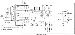
Hope this will help.It's one of the many version but the amp is basicaly the same and so the voltages (I hope 😀 )
Mona
Actually I think I saw this as the Series II, and yes I appreciate it. That will probably come in handy.
I'll work on getting the -75V supply side figured out.
Maybe a small filament transformer with two 12.6VAC windings (or one 25.2VAC winding).
If you connect those in series and do a voltage doubler, you'll get around 68VDC,
which is close enough.
Last edited:
What is the value of choke L1?Hope this will help.It's one of the many version but the amp is basicaly the same and so the voltages (I hope 😀 )
Mona
Thanks a bunch!
Looks like I'm on track for starting with the DC-DC supplies I ordered (+450V, 75-600V adjustable).
I'll work on getting the -75V supply side figured out.
Go down to WM and get a 250W inverter.
Go down to WM and get a 250W inverter.
Hi, I played around with the "average" AC inverter, and they're prone to shutting off when attempting to power a large transformer.as I discovered.
I could use a true sine wave inverter, but using that big, heavy, and expensive power transformer is something I'd prefer to avoid (and true sine wave inverters are not cheap either). Milbert also uses switching supplies in their very nice BAM 23ab car tube amp.
Did it trip out from high surge, or low voltage? Where did you make the connection, cigarette lighter, or direct battery connection with the engine running, or stand alone battery?
Did it trip out from high surge, or low voltage? Where did you make the connection, cigarette lighter, or direct battery connection with the engine running, or stand alone battery?
I'm pretty sure it was from the initial inrush current. That was powered directly from a fully charged battery at the time I it.
I'm pretty sure it was from the initial inrush current. That was powered directly from a fully charged battery at the time I it.
Ok, well it wouldn't be the transformer causing an inrush that trips the high current protection, it would be because of solid state rectification into a high capacity filter, plus the heater load. The ST-70 draws 190W or less running, but until the 5AR4 starts up there is only heater current being drawn. So if your inverter has enough capacity watt-wise it ought to not trip off from the initial turn on of a tube rectified ST-70. It might take a 350W inverter or one rated with enough peak load. The amp uses a 3W fuse. Good luck with your project.
- Status
- Not open for further replies.
- Home
- Amplifiers
- Tubes / Valves
- Looking for Dynaco ST-70 Power Supply Info/Specs