Hello All,
I am still very new to this, so please let me know if I am missing any critical information.
Anyhow, I just assembled an F5 clone (actually, I just populated the boards, Jim (6L6) made it an actual amp).
Currently using a passive line-stage (input selector, passive attenuation with an Alps vol pot).
The problem is that my phono pre, and I suspect my Sonos as well, do not have enough output voltage to fully drive the F5 - I think the F5 reaches full output at 3.5 volts, but not totally sure.
My phono amp has 44 db of gain (Vacuum Tube Audio PH14 phono preamp) and I am using an Ortofon 2M Bronze. Not sure what the final output voltage is.
The Sonos has a max of 2 volts.
Please, I don't want this to become a thread about the need/merits of another gain stage vs passive, I am just looking for advise (schematic with some explanation of how to implement) for something I can put together easily (remember, I am a noob, and can barely read a schematic) and cheap.
Therefore, I guess my requirements are as follows:
1) I do NOT need massive gain
2) Cheap, simple design
3) Prefer something small (I already have a fairly small box the passive is in that I would like to use for this)
4) Something that can be powered with a wall-wart would be GREAT! Saves on space and cost for me
Any help is greatly appreciated.
Thanks!
Matt
BTW - I will eventually build something like an Akido, but have to wait before investing another few hundred bucks into another project (wife has limits to her patience). Ergo, this request for something cheap to get me buy for the next several months.
Could you provide a link to the Sonos with specs, I don't want to search the website, which is a complete PITA, it wants me to pretend to buy one before it'll tell me anything.
A diagram of the system with where you intend to put the gain stage would help. Do both inputs achieve comparable levels?
A diagram of the system with where you intend to put the gain stage would help. Do both inputs achieve comparable levels?
Here is the Sonos link (they don't provide the specs you or I would care about, I had to call customer support to find out the max output voltage is 2 volts - I didn't think to ask anything about impedance or anything else at the time)
Sonos CONNECT Wireless HiFi Player
Yes - the phonostage and Sonos (digital streamer) have comparable output levels.
I don't have the ability to draw and post a scheme right now, but it would be as follows:
Phono to linestage input 1 (remember I currently have a passive line stage with two inputs, a rotary selector switch, a passive volume (attenuation) and then two outputs - one to the F5, the other to my sub).
Sonos to linestage input 2.
Linstage outputs to amp and sub.
I intend to put the gain stage in the passive linestage box with the gain circuit after the volume pot. (thus changing it from a passive linestage to an actual preamp).
The chassis (box) should be big enough for the circuit - right now it is effectively an empty box with RCA jacks on the back and two knobs on the front.
.
Sounds to me like a classic case. Google for:
NE5532 preamp
These are available on eBay for around $15, but remember that you'll need a power supply, and also a housing of some sort.
Or you can build one yourself for maybe around $20 including the power supply, but not including a housing. RadioShack's 450ma transformer #2264950 goes for $8, at this writing on sale for $6.
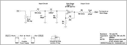
If you're interested in building a preamp yourself, everybody in the world has an NE5532 preamp circuit that will show up in your Google search. I'm posting mine below (largely a shameless rip from D. Self), circuit notes follow.
CIRCUIT NOTES:
Rvol is, of course, the volume control. Together with R2 it sets the circuit input impedance (Zin). Zin is the parallel value of Rvol and R2 (Rvol || R2), here about 25k.
R1 and C1 together form a low-pass filter that shunts ultrasonic frequencies to ground. This takes a bit of load off the op amp (because it doesn't have to amplify those frequencies), and helps prevent feedback.
C2 and R2 together form a high-pass filter, which here rolls off frequencies below about 20Hz. R2 also sets Zin as previously noted.
R3 and R4 set the op amp gain according to the formula Gain = 1 + (R3/R4). Gain can theoretically be almost anything, but in real-world terms it's probably best to stay below a gain of around 20. Note that R3 and R4 are actually part of the op amp, made exterior to allow gain adjustment.
R5 is commonly included in circuits, it prevents problems with capacitance in the output line.
Cout is a DC blocking capacitor. Op amps are not perfect, they have various errors that are amplified along with the audio signal. Cout solves all problems in a shotgun manner by allowing only the audio signal to reach the output line. The 470uF value is commonly specified for good bass response. Note that if you're sure the following stage has a capacitor on its input ("AC coupled"), then Cout can and should be omitted.
Building Notes: Problems are unlikely, largely because the NE5532 is near-bulletproof. Keep components as close together as your skill level reasonably allows. The circuit could be very small, but there's no need to obsess about it. Importantly, keep audio signal conductors away from power supply conductors. Do not allow the audio signal to mix with the power supply voltages except at circuit ground.
Except for transformers (which they don't sell) I've had good results using this eBay seller: 1 4W 5, Ceramic Disc Capacitors items in Thai Shine store on eBay! Disclosure: I have no association with these people except to send them money sometimes.
.
Sounds to me like a classic case. Google for:
NE5532 preamp
These are available on eBay for around $15, but remember that you'll need a power supply, and also a housing of some sort.
Or you can build one yourself for maybe around $20 including the power supply, but not including a housing. RadioShack's 450ma transformer #2264950 goes for $8, at this writing on sale for $6.
If you're interested in building a preamp yourself, everybody in the world has an NE5532 preamp circuit that will show up in your Google search. I'm posting mine below (largely a shameless rip from D. Self), circuit notes follow.
CIRCUIT NOTES:
Rvol is, of course, the volume control. Together with R2 it sets the circuit input impedance (Zin). Zin is the parallel value of Rvol and R2 (Rvol || R2), here about 25k.
R1 and C1 together form a low-pass filter that shunts ultrasonic frequencies to ground. This takes a bit of load off the op amp (because it doesn't have to amplify those frequencies), and helps prevent feedback.
C2 and R2 together form a high-pass filter, which here rolls off frequencies below about 20Hz. R2 also sets Zin as previously noted.
R3 and R4 set the op amp gain according to the formula Gain = 1 + (R3/R4). Gain can theoretically be almost anything, but in real-world terms it's probably best to stay below a gain of around 20. Note that R3 and R4 are actually part of the op amp, made exterior to allow gain adjustment.
R5 is commonly included in circuits, it prevents problems with capacitance in the output line.
Cout is a DC blocking capacitor. Op amps are not perfect, they have various errors that are amplified along with the audio signal. Cout solves all problems in a shotgun manner by allowing only the audio signal to reach the output line. The 470uF value is commonly specified for good bass response. Note that if you're sure the following stage has a capacitor on its input ("AC coupled"), then Cout can and should be omitted.
Building Notes: Problems are unlikely, largely because the NE5532 is near-bulletproof. Keep components as close together as your skill level reasonably allows. The circuit could be very small, but there's no need to obsess about it. Importantly, keep audio signal conductors away from power supply conductors. Do not allow the audio signal to mix with the power supply voltages except at circuit ground.
Except for transformers (which they don't sell) I've had good results using this eBay seller: 1 4W 5, Ceramic Disc Capacitors items in Thai Shine store on eBay! Disclosure: I have no association with these people except to send them money sometimes.
.
Attachments
Last edited:
Thanks Bentsnake!
I spend all last night looking at the Jfet BOZ... getting the jfets may be a pain.
I spend all last night looking at the Jfet BOZ... getting the jfets may be a pain.
Snake - your schematic has a note to bypass the power pins (assuming you mean 4 and 8) with some caps.
I'm confused - isn't this where I attach the power supply?
Also, can I use a wall-wart instead of the two 9v batteries?
Thanks!
Matt
I'm confused - isn't this where I attach the power supply?
Also, can I use a wall-wart instead of the two 9v batteries?
Thanks!
Matt
Snake - your schematic has a note to bypass the power pins (assuming you mean 4 and 8) with some caps.
I'm confused - isn't this where I attach the power supply?
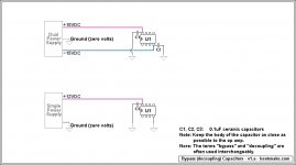
You're correct, power goes to pins 8(+) and 4(-). My note is unclear.
Explanation: The 0.1uF bypass capacitors are connected to the power pins also, one to each power pin, connected between the power pin and ground. So there are two bypass capacitors for each op amp. Their purpose is to shunt (bypass) certain types of noise to ground, keeping the DC power supply voltages clean.
Strictly speaking these bypass caps are always required, so they don't always appears on schematics (such as mine). It's simply assumed that you know to add them.
These caps very commonly are ceramic, but some people like to use film types and that's fine.
Making things a bit complicated, some schematics do show the bypass caps, usually called out as 100nF (same as .1uF). So if you see a 100nF capacitor connected to a power pin, that's what it is, don't add another one.
Now contradicting everything I've said above, there's not universal agreement about using bypass caps, some consider them of no value.
In can be argued that in a very low power circuit such as this they do nothing useful, and they do crowd the busy area around the op amp. So my suggestion is to leave them off if you find them very difficult to install, otherwise include them.
In an important FYI, similar capacitors appear in the power supply, again usually called out as 100nF. Very irritatingly, the terms "bypass" and "decoupling" are used interchangeably for all these caps. This confusion of terms has achieved wide usage, so you just have to look at the schematic to see what's what.
.
Last edited:
can I use a wall-wart instead of the two 9v batteries?
Note "possible" power supply. The two 9 volt batteries are just illustrative. Any power supply of the correct voltage(s) can be hooked to pins 8 and 4.
You can run most op amps on a single--as opposed to dual--power supply. Paste this into Google, including quotes:
"single supply" NE5532 circuits
However, in my view single supply circuits are more trouble than they're worth, due to added components and possible additional noise--although, as always, others will differ.
It seems many use wall warts successfully, but I personally have had just terrible luck with them. Some I've tried wouldn't quiet down no matter what I did, and I have no idea why. Finally I just gave up on the whole idea.
So yes I'm sure you can use wall wart power, but I'm not the guy to ask about it. I hope somebody who knows more will come along.
.
Thanks!
Now I'm confused again - can't I just use one op amp? pins 1, 2, and 3 for one channel and pins 5, 6, and 7 for the other?
So there are two bypass capacitors for each op amp..
Now I'm confused again - can't I just use one op amp? pins 1, 2, and 3 for one channel and pins 5, 6, and 7 for the other?
Now I'm confused again - can't I just use one op amp? pins 1, 2, and 3 for one channel and pins 5, 6, and 7 for the other?
Yes, and it's expected that you'll do that.
There are two bypass caps for each op amp because there are two power pins. Remember that the bypass caps have to do with the power supply circuit, they in no way relate to the audio circuit(s). So you'd hook power to pins 4 and 8, and also bypass these pins.
The op amp is now powered, and you can use the two audio circuits inside it for any purpose you like, whether or not the two circuits have anything to do with each other.
BUT if you do use a single supply, then then only pin 8 receives + power, while pin 4 is grounded. In that case you'd bypass only pin 8.
.
Last edited:
Yes, and it's expected that you'll do that.
There are two bypass caps for each op amp because there are two power pins. Remember that the bypass caps have to do with the power supply circuit, they in no way relate to the audio circuit(s). So you'd hook power to pins 4 and 8, and also bypass these pins.
The op amp is now powered, and you can use the two audio circuits inside it for any purpose you like, whether or not the two circuits have anything to do with each other.
BUT if you do use a single supply, then then only pin 8 receives + power, while pin 4 is grounded. In that case you'd bypass only pin 8.
.
Cool. Thank you so much for your help!
... getting the jfets may be a pain.
Not really - half a buck at Digikey:
BF862,215 NXP Semiconductors | 568-1968-1-ND | DigiKey
Here it is: cheap, simple, small, has about 10dB of gain, works of a 24V DC wall wart (consumes about 10mA per channel), sounds better than simple OpAmp circuits and drives F5 with ease. Shoud have about 12V at Drain - if much less, increase R2.
Attachments
Thank you so much for your help!
You're welcome, glad to help out a bit.
Still, I never pass up a chance to over-explain things, so I'm posting the below illustration. Just to make things, I hope, entirely clear.
.
Attachments
You're welcome, glad to help out a bit.
Still, I never pass up a chance to over-explain things, so I'm posting the below illustration. Just to make things, I hope, entirely clear.
.
Thanks! Yes, that is VERY helpful as I am totally new to this.
Not really - half a buck at Digikey:
BF862,215 NXP Semiconductors | 568-1968-1-ND | DigiKey
Here it is: cheap, simple, small, has about 10dB of gain, works of a 24V DC wall wart (consumes about 10mA per channel), sounds better than simple OpAmp circuits and drives F5 with ease. Shoud have about 12V at Drain - if much less, increase R2.
THis is great, thanks!
A couple of questions:
1) where does the negative from the power supply (wall wart) hook up to the circuit?
2) for Q1 http://www.digikey.com/product-detail/en/BC547CTFR/BC547CTFRCT-ND/3504423
What pins connect to which resistors?
3) For the resistors and caps - what voltage and wattage ratings?
I think I may build both the jfet and opamp circuits (they are so cheap) and see which works best in my system.
Thanks!
Matt
Uffffffffffff....
Imagine a guy coming into a car workshop and says: OK, I want to build a car. Now, tell me what is this and why do you call it a wheel ?
That guy is you.
Sorry, but if you don't know what
 is and the schematic symbol of BJT is a mystery to you, I think I won't be able to help you. You'll have to read some basic electronic textbooks first.
Imagine a guy coming into a car workshop and says: OK, I want to build a car. Now, tell me what is this and why do you call it a wheel ?
That guy is you.
Sorry, but if you don't know what
Re: 1), see above post.
Re: 2), the first thing to do in such cases always is consulting the datasheet. "Euro" small-signal transistors like that usually have an EBC pinout. When looking on the flat side, the emitter is on the right.
Re: 3),
Rs usually are 1/4 W (typically metal film) unless noted. It wouldn't hurt to use a 1/2 W for R5.
Capacitors need to sustain at least the voltages present over them in operation - about 3.3 V at C2 (--> 6.3 V minimum), close to full supply at C3 (--> 25 V at the very least, and a film type may get so large that a bipolar electrolytic of maybe 10µ/50V would be a better choice), and about full supply at C1/4/5 (--> 35 V or higher).
Measured performance is expected to be a fair bit better on the 5532-based circuit (for the simple reason that a single FET even at ~10 mA of Id has some difficulty competing with a reasonably complex opamp circuit at 4 mA per channel). Should you happen to have a half-decent soundcard that is set up properly, you could run some distortion measurements, at least at levels that the input will still accept (typically 1-1.4 Vrms for onboard, 1-2 Vrms for dedicated cards).
Last edited:

- Status
- Not open for further replies.
- Home
- Source & Line
- Analog Line Level
- Looking for a Cheap, simple Opamp gain stage