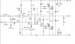
this schematic is from bora legend 4 which i changed resistors that feed vas amp MJE340 in order to maintain 5.5 ma curent flowing from it and finally operate at 66+66 volts ....
all my changes are marked in red and the original value of the resistors where 4K7 and another 4K7 plus the input capacitor that was 1mfd and plus thecapacitor of vas amplifier that originally didnt exist
all these mods where done to work the amp at 66+66 volts
your opinion is very welcome thank you
east_electronics@yahoo.gr
Attachments
0.18 ohm resistors should be in the sources of the bottom MOSFETs, not the drains. +-66V would give you quite a bit more power than two pairs of MOSFETs would like, if you want reliability...
Hi,
A pair of IRFP250 needs about 3,3mA gate current at 20kHz. So I would choose higher VAS current, say 10mA. (change 6k8 > 3k0/1W)
Then with 3k0+3k0 "CCS-resistors" I'd change 470uF bootstrap cap to 100uF.
Your actual gain is 27dB, so for 200W/8 Ohms you'll need 1,8V. I would rather choose 1V input sensitivity.
What is the purpouse of the serial resistor (looks 620R) between VAS transistors collector and the Vbe multiplier?
And what about the 680R (?) resistorbetween the Vbe multiplier and the upper output fet's gate reistors?
The low-freq rolloff in the feedback loop is 0,7Hz. That's OK.
But in the input 0.47uF and 10K gives 34Hz! That's need to be divided by ten, 3,4Hz will be just perfect. So change input capacitor to 4,7uF.
Your LTP's tail current iis now 6,6mA. That's too much! 2mA would be OK. So change 10K tail resistor to 33k.
Or give your LTP a real CCS. That will dramatically increase the PSRR of your amplifier (now with that RC-filter and single resistor CCS the PSRR is bad - I'm sure.)
VAS's BE-resistor's value (680R?) is false. With 66V rails and 10k tail resistor 200R would be the OK value. With the 33k modification suggested by me the 680R value is just OK.
- Status
- Not open for further replies.
