Hi,
I would like to propose an extrerme version of a circuit I'm working on as a driver.
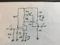
It uses local current feedback to increase the gain of the stage, and bootstrap from the source of the source follower to have a CCS-like loadline.
I'll use lower gain in the real circuit (lower value for R17, then adjust R2 and R3 to center the working point), but in simulations I've got up to 55 dB of gain with 3% THD at 300 Vpp with 180 mVrms at the input. The source follower works at 3 mA.
Has anyone played with something similar?

Thanks
Roberto
I would like to propose an extrerme version of a circuit I'm working on as a driver.
It uses local current feedback to increase the gain of the stage, and bootstrap from the source of the source follower to have a CCS-like loadline.
I'll use lower gain in the real circuit (lower value for R17, then adjust R2 and R3 to center the working point), but in simulations I've got up to 55 dB of gain with 3% THD at 300 Vpp with 180 mVrms at the input. The source follower works at 3 mA.
Has anyone played with something similar?
Thanks
Roberto

http://www.valvewizard.co.uk/dccf.html
Check bottom of the page.
Works very well, either with tubes or a MOSFET as a follower. 🙂
Check bottom of the page.
Works very well, either with tubes or a MOSFET as a follower. 🙂
Thanks @wg_ski , I didn't know that tube. What i the ratio between 2nd and 3rd harmonic with that configuration?6JW8 tri/pent to give gobs of gain and low Z out.
That's a simple bootstrap. You can't exceed the mu of the tube with that configuration.
I was probably confused about the second post. Which is also a regular bootstrap.That's a simple bootstrap. You can't exceed the mu of the tube with that configuration.
In your original post I didn't see the difference in cathode connection, sorry.
The regular bootstrap will give a gain close to the mu of the tube.
Yes, the bootstrap makes the signal at the two ends of the bottom load resistor the same, so the load of the previous stage to become virtually a CCS, so the gain close to mu.
I just simulated your circuit in the start post with two triodes.Yes, the bootstrap makes the signal at the two ends of the bottom load resistor the same, so the load of the previous stage to become virtually a CCS, so the gain close to mu.
I don't get more gain than a regular bootstrap, in fact I even get a little less.
Only with a MOSFET you will get more gain, although the frequency bandwidth might be suffering.
Since we are working here with a hybrid approach with solid state, I usually just use a LND150 as a "trioderizer".
Meaning, giving it local negative feedback. The loadlines will be very much like a triode, and a total gain of like 100-120 is very easy to do 🙂
Can you post the two circuits you used?
Yes, bandwidth will suffer as with all positive feedbacks, but with 1k grid stopper you can raise the gain well beyond mu without problems.
Miller capacitance increases with gain.
Yes, bandwidth will suffer as with all positive feedbacks, but with 1k grid stopper you can raise the gain well beyond mu without problems.
Miller capacitance increases with gain.
Not sure about the ratio, but it’s definitely dominant 2nd harmonic. I‘ve run it open loop playing with geetar amps, where bandwidth can be limited, but for hi-fi I run it with local feedback. Very low distortion closed loop with gains of less than -10, and surprisingly low noise. What I wanted was a good single bottle Baxandall tone control - tried this, and hey - I like it. Let’s keep using it.Thanks @wg_ski , I didn't know that tube. What i the ratio between 2nd and 3rd harmonic with that configuration?
I like it!

In simulation:
R2 and R1 above yield 5X gain. That's a lot of NFB.
THD of 1kHz sine wave into 100k load at 2V RMS output = 0.0062%. 3rd harmonic is theoretically about 20dB lower than 2nd.
Drives a 10k ohm load just fine. No loss of gain.
I've attached the .asc so you can play with it.
In simulation:
R2 and R1 above yield 5X gain. That's a lot of NFB.
THD of 1kHz sine wave into 100k load at 2V RMS output = 0.0062%. 3rd harmonic is theoretically about 20dB lower than 2nd.
Drives a 10k ohm load just fine. No loss of gain.
I've attached the .asc so you can play with it.
Attachments
All of a sudden R1 appeared? 😀 😀
btw, it only gives about 14dB of gain?
I think you wanna change R2 or R1?
btw, it only gives about 14dB of gain?
I think you wanna change R2 or R1?
Whatever it is, the whole purpose was about getting more gain than a standard bootstrap circuit?That's for the shunt NFB. I'll post it open loop. One sec...
Going so low on the cathode resistor (R3) is also not that great I think?
Open loop it looks like it can deliver 440X gain -- !!!! 😱 !!!!
At 2V RMS out, 6.38mV 1kHz sine wave input, driving a 100k ohm load, it makes 0.09% THD.

However, the bandwidth leaves something to be desired.

It's pretty much unusable without NFB. But with that much gain, it just begs for NFB.
--
At 2V RMS out, 6.38mV 1kHz sine wave input, driving a 100k ohm load, it makes 0.09% THD.
However, the bandwidth leaves something to be desired.
It's pretty much unusable without NFB. But with that much gain, it just begs for NFB.
--
Last edited:
The problem with NFB is that small amounts of it suck. You either want a lot of it, or none at all. This can give a lot of OLG (and therefore amount of NFB) while still actually being able to drive something.
440x with a triode. Now try it with a pentode.
440x with a triode. Now try it with a pentode.
I was wondering why there's no grid leak resistor for the 12AX7 in post #1. Simplified schematic, so not 100% necessary to show it? Or was that done on purpose? If on purpose, what's the reason? I put a grid leak in there and it didn't change anything, so I figure it should be there to inhibit grid current, etc. No?
By changing che local positive current feedback, you can adapt not only the sensitivity of the driver, so of the amp, to your needs, but also the harmonic content of the driver at the desired output swing, so you can EG tailor-chase the 2nd harmonic cancellation.Zintolo
Was wondering how you propose to hook your circuit up to say a SE power stage?
As I was writing in the first post, my purpose is to use it with less gain (lower Rk) for Hi-Fi purposes where two driver stages can be too much and one stage not enough.
Even higher local positive current feedbacks (Rk around 1k) and lower bootstrap capacitors (around 22n) can be used in guitarland to increase the gain while toneshaping frequencies (lower the gain of lows and highs).
- Home
- Amplifiers
- Tubes / Valves
- Local CFB and bootstrap: an hybrid 12AX7 driver with 55db of gain and CF-like Zout