I ordered this pre amp kit and it arrived today.
Stereo Tone Control 3 Way Audio Preamplifier Kit Bass Mid Treble Analog | eBay.
the documentation is here www.siliconwiz.com/k330/doc.pdf
Really small 2 1/2" by 3 3/4". Almost too small for my plans.
I ordered this because to me it looked like a decent pre amp.
It uses LME49720 which seem to be great chips, seems to have above average capacitors.
I like the tone controls where they are (60hz 1k and 8 k), and it came from New York.
I may need to order a power transformer since this thing only requires 65ma and they recommend a 17 volt which would be hard to find so I'll probably look for a 15-0-15 supply.
Suggestions greatly appreciated, I'm a noob who prefers to just assemble kits and leave the designing to those who enjoy all of that math.
Thanks
The LME49720 is a great opamp and has a maximum rating of 36v (-/+18) and anything up to +/-17v is good.
A simple supply can be made using a LM7815 and a LM7915 TO-220 packaged regulators.
The LME49860 is even better and is good for +/- 22v max.
jer 🙂
A simple supply can be made using a LM7815 and a LM7915 TO-220 packaged regulators.
The LME49860 is even better and is good for +/- 22v max.
jer 🙂
I just ordered one of these to add line inputs to a guitar amp I am building. I'll probably run it on +/- 15 volts derived from the heater supply.
I'll have to read up about using LM7815 and a LM7915 for a power supply.
I'll probably start off minimal gain but still want a power supply 15-17 volts.
I'll probably start off minimal gain but still want a power supply 15-17 volts.
I just ordered one of these to add line inputs to a guitar amp I am building. I'll probably run it on +/- 15 volts derived from the heater supply.
I've thought about this for a small practice bass rig going to a tda2050 or LM1875 chipamp. On that I would change the crossovers, maybe use slider pots to imitate an eq .
Have to build this one 1st.
The LM78xx and 79xx regulators are very easy to work with and don't require huge filter capacitors.
bipolar power supply - Google Search
Radio shack has some small 25.2v center tapped transformer that will work.
http://www.radioshack.com/product/index.jsp?productId=2102701&locale=en_US
This one should be able to power your preamp and a small chipamp,
http://www.radioshack.com/product/i...ce=CAT&znt_medium=RSCOM&znt_content=CT2032230
jer 🙂
Last edited:
I have several of those 2 amp radio shack transformers, when they decided to get out of electronics they were selling them for 2 bucks, even today they are a good price and they are shielded too.
I'll probably go buy one of the smaller MA transformer since this is suppose to draw a maximum of 65ma.
I have a choke but it is only rated for 50ma.
I'll probably go buy one of the smaller MA transformer since this is suppose to draw a maximum of 65ma.
I have a choke but it is only rated for 50ma.
WoW.....2 bucks !!!
That is a good deal.....Had I known that I would have gotten a bunch more of them!!!
I have used those for years in many projects and I just used my last one in my variable 0v to 13.5Kv power supply.
The Opamp won't draw any more than about 25ma. worst case and typically about 10ma. under normal use as a preamp.
That transformer will give you +/- 17.8V I used a couple of diodes in series feeding each rail of the opamp to drop the voltage for a safe level in order to not fry the chip.
Two diodes in series will give you aproximately 1.1v to 1.3v drop.
Do measure the voltage First by loading the supply with a 1K to 5K resistor to ground before hooking up the preamp and if it is to high add another diode.
That is the cheap and quick method should you not have any regulators on hand.
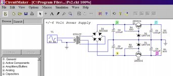
Here is the schematic,
http://www.diyaudio.com/forums/plan...tor-insulation-mylar-coating.html#post2848194
jer 🙂
That is a good deal.....Had I known that I would have gotten a bunch more of them!!!
I have used those for years in many projects and I just used my last one in my variable 0v to 13.5Kv power supply.
The Opamp won't draw any more than about 25ma. worst case and typically about 10ma. under normal use as a preamp.
That transformer will give you +/- 17.8V I used a couple of diodes in series feeding each rail of the opamp to drop the voltage for a safe level in order to not fry the chip.
Two diodes in series will give you aproximately 1.1v to 1.3v drop.
Do measure the voltage First by loading the supply with a 1K to 5K resistor to ground before hooking up the preamp and if it is to high add another diode.
That is the cheap and quick method should you not have any regulators on hand.
Here is the schematic,
http://www.diyaudio.com/forums/plan...tor-insulation-mylar-coating.html#post2848194
jer 🙂
here in Ohio those 2 amp 12.6-0-12.6 are giving me 30 volts with 125 volts at the outlet.
I stopped at 2 radio shacks today. The 1st one had 0 transformers, the guy took me to the wall wart section. The send store had an older clerk and took me right to them so I bought 1.
I'll start soldering on this project in the morning.
I should order some better pots.
I stopped at 2 radio shacks today. The 1st one had 0 transformers, the guy took me to the wall wart section. The send store had an older clerk and took me right to them so I bought 1.
I'll start soldering on this project in the morning.
I should order some better pots.
Hmmm.......... Your line voltage is high in your area.
If it fluctuates that much your better off using some regulators.
Is that 30V AC out of the transformer?
If so that will give you +/- 21.2Vdc, a bit to high!!
+/- 15V is plenty enough for a preamp.
You can get as much a 25Vp-p on that much voltage and I doubt you will ever need more than half of that.
Even +/-12v is enough using a LM7812/7912 regulators.
You could even use a simple zener diode regulator as well using a pair of 15v zener's and two resistors.
jer 🙂
Last edited:
I bought the several of 12.6 -0-12.6 2 amp transformers and I picked up around 10 of the line transformers for speakers back when Radio Shack was doing their close outs. The speaker transformers work for 50c5 amps. Then things got busy and I never managed to build anything.
yes the voltage here is too high here, it is steady but every meter I have put in every outlet says 125 and it doesn't drop. I'm renting this house and when we moved in I had to reconnect every outlet as someone had wired them up with the screws pressing on the wire and the insulation.
Wife heard a buzzing noise the 1st day and after I saw that I checked every outlet.
Had to change 3 of them due to the extra heat over the years had melted those sockets just a tad.
The garage was newer wiring, no grounds connected, a couple outlets were out of phase.
It is all good now.
Thanks for letting me know 12 or 15 volts is enough, I'm building this with minimal gain.
I'm also waiting on 2 boards of a much simpler NE5532 pre amp and 1 phono section.
This pre amp looked like a decent price. My only complaint so far is the mounting holes are small (3mm) so I have to find some stand offs before I can mount this in a case.
The NE is another excellent and very quiet opamp.
Although it is aged it does hold its own to many of today's counterparts.
I replaced all of the opamps in my first mixer (Fostex 454) with them and used the TL072's for the filters and the thing was dead quiet and gave my newer (at the time) Mackie 32-8 a run for the money.
In fact we really couldn't tell the difference between the two on a unEQed signal.
Now the NE5532's can be found for about $.35 to $.45 a piece and back then they were nearly 10 times that!!!
I have also used some good ole clear silicone rubber to mount boards with at times.
It works very good for such applications as long as it is something that doesn't need to be taken apart, Standoff's are much nicer!! 🙂
Here is the data sheet to the LME49720,
http://www.ti.com/lit/ds/snas393c/snas393c.pdf
On pages 20&21 show the output voltages characteristics of the opamp and on page 21 it shows the output voltage swing in Vrms vs supply voltage.
For peak values just multiply the Vrms value by the square root of 2 or 1.4142.
These are typical for most any common opamp although they do vary slightly.
For instance I only can get about 12.5Vpeak (25Vp-p) as measured with a LME49860 on a +/- 15v supply but it is still way more than enough for a preamp stage.
On a +/- 12V supply you will get about a 8Vrms output even in to a 600 ohm load.
Jer 🙂
Last edited:
The NE is another excellent and very quiet opamp.
Although it is aged it does hold its own to many of today's counterparts.
I replaced all of the opamps in my first mixer (Fostex 454) with them and used the TL072's for the filters and the thing was dead quiet and gave my newer (at the time) Mackie 32-8 a run for the money.
In fact we really couldn't tell the difference between the two on a unEQed signal.
Now the NE5532's can be found for about $.35 to $.45 a piece and back then they were nearly 10 times that!!!
I have also used some good ole clear silicone rubber to mount boards with at times.
It works very good for such applications as long as it is something that doesn't need to be taken apart, Standoff's are much nicer!! 🙂
Here is the data sheet to the LME49720,
http://www.ti.com/lit/ds/snas393c/snas393c.pdf
On pages 20&21 show the output voltages characteristics of the opamp and on page 21 it shows the output voltage swing in Vrms vs supply voltage.
For peak values just multiply the Vrms value by the square root of 2 or 1.4142.
These are typical for most any common opamp although they do vary slightly.
For instance I only can get about 12.5Vpeak (25Vp-p) as measured with a LME49860 on a +/- 15v supply but it is still way more than enough for a preamp stage.
On a +/- 12V supply you will get about a 8Vrms output even in to a 600 ohm load.
Jer 🙂
P.S. 12.5Vpeak (25Vp-p)= 8.8375Vrms
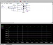
Built the Power supply today.
Line voltage was 120 volts today, (averages 120-125) with 120 volts going into a 6.3-0-6.3 1.2 amp transformer output is 13.9 (radio shack quality there)
After a bridge rectifier then 2- parallel 3100uf caps. with 1 resistor of 220 ohms from each rail to ground to simulate a load of 65ma. My voltage was 18.5 volts.
Using a scope I'm pretty sure I was seeing .04 voltage ripple. (I'm new with oscilloscope)
That voltage is too high, I was hoping for 17v max preferably 15v.
Should I put the dropping resistors before the capacitors, between the capacitors of after the capacitors and what would be a good starting point.?
I've tried to use PS designer and LTspice. I'm getting nowhere with those.
I can't get PS designer to show me a dual rail power supply and both programs want an ohms reading on the capacitor.
Meanwhile, time to start soldering the board up.
The dropping resistor method is dependent upon how much current is drawn from the opamp.
The more current the opamp draws the greater the voltage drop will be across the resistor.
Using series diodes guaranty's a certain amount of voltage drop regardless of the current draw providing you don't exceed the diodes current rating.
I have burned quite a few of them in one shot before due to an accidental short on the line.
Although using a series current limiting resistor would have saved them.
When using diodes, it is best to match them up using the Diode Checking function on your meter as the readout will tell you what your voltage drop will be on the particular diode that you are testing.
Then you just add up the numbers for each diode in the chain and this will give you what your total voltage drop will be.
Make sure though that you do account for rise in the power line level.
From what you have said this could actually be quite a large number of diodes needed to drop the voltage and using a pair of regulators would be more cost effective.
For the measurement you have posted 2,3 or 4 diodes will be enough unless the line voltage has a considerable rise.
Using regulators will also give you better noise rejection from the power supply as well.
Although 40mv of ripple is just fine because the power supply rejection ratio of the opamp is very high.
When using spice you must supply a reference to ground with capacitors that have ends that go nowhere or have no current flow.
A resistance such as 1meg to ground is ample if you don't want any excess current draw from that portion of the circuit to be calculated.
So when designing power supply you must also include a load resistance or it will error.
jer 🙂
Thanks, I do have LM317 and LM117 regulators. I was hoping I could do a simple power supply like on power amps but the voltage here is all over the place so better safe then sorry.
The 1 advantage to making my own power supply is I don't need a magnifying glass with light to solder it up 🙂
This pre amp board is tiny.
The 1 advantage to making my own power supply is I don't need a magnifying glass with light to solder it up 🙂
This pre amp board is tiny.
You could use a single positive regulator but you would have to setup a virtual ground system.
Or get a LM337 the negative version of a LM317.
If you have any of the LM78xx or 79xx regulators these can be made to regulate at higher voltages as well by adding a resistor to the ground and pin2 common input pin.
What this does is it raises its ground reference level to a higher voltage above ground and will still regulate but at a higher voltage.
jer 🙂
http://www.diyaudio.com/forums/power-supplies/53359-finished-capacitance-multiplier.html
I am waiting on 2 of these boards, I'll use one for this project. Should be more then enough
I soldered the resistors , chip sockets and 4 caps last night.
I was short 4 resistors but I am well stocked and the kit has 12 extra so decent trade.
This board made me realize I need a smaller tip for my hako soldering station.
- Status
- Not open for further replies.
- Home
- Source & Line
- Analog Line Level
- LME49720 Pre amp PCB/Kit