There was no problem with this. All tested opamps were stable. Only the compensation capacitors for some OPAs had to be increased. I use it mostly with the lowest voltage gain settings. OPA is SS3602 Sparkos, it sounds best in this set.The issue you have won’t arise in a line amp if you are driving the output directly from the opamp via a 47 to 100 ohm resistor.
Attachments
You are feeding an opamp into an OPS that is introducing additional phase shift. You should comp the opamp as I mentioned above otherwise you can never guarantee stability across a wide range of capacitive loads. The 120 Ohm resistor in series with the mosfets input capacitance is introducing a pole and associated phase shift.
Please add output caps, muting and input filtering to the "Pretpojačalo" otherwise you make the same mistakes as were made in the other device. Or add a DC servo and muting. And when sources have DC offset input caps are a necessary pain too.There was no problem with this. All tested opamps were stable. Only the compensation capacitors for some OPAs had to be increased. I use it mostly with the lowest voltage gain settings. OPA is SS3602 Sparkos, it sounds best in this set.
Point being that one needs to carefully find out how the used sources and power amplifier have been constructed. Two caps in series is not OK but no cap at all and amplified DC offset aren't either. Proud numbers of bandwidth in the MHz region have no positive practical use. Do the cell phone test near DIY devices.
Having seen DC servos going mad in fully DC coupled chains various times and also DIY devices suddenly putting out DC my advice is to keep at least 1 input cap per channel in the power amplifier.
Last edited:
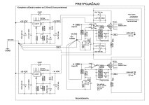
It's just a schematic of the preamplifier (pretpojačalo). I have a mute circuit with delay on switching on, immediate shutdown when switching off, and in some stronger versions I put complete DC protection by @miro1360. The bottom line was to make a cute little preamp, and I did that.
Attachments
Still the suggestions were well meant and usable I think. Input filtering, muting and DC protection are good design practice but omitting either seems fashionable in circles.
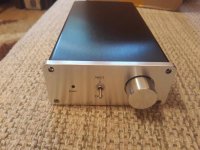
Pff all this time and energy for a device practically superfluous in 2024 🙂 Ah pictures have been added. Some advice you may ignore if you want:
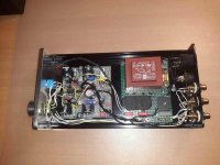
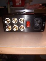
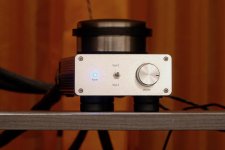
Looks nice but both the power switch, EI type transformer and the rectifier bridge are too close to the RCA connectors IMHO. Power switch (at the back?!) can be situated at the spot where the terrible blue LED is now situated. Metal tube can be used to route the cabling through. I was ill for a time and learned myself to draw PCBs again with KiCAD and I can recommend it. Then the power switch can be designed in on the PCB. If the PSU would be located at the front volume control and source selection (with a relay) and volume control with an extension rod can be situated as close as possible to the RCA connectors. Shortest signal path, shortest possible wiring, no signal wiring near/crossing supply wiring, everything sensitive farthest away from the transformer/PSU. Win-win-win-win.
For that purpose I made small 2 input relay boards. Works perfectly.
Last edited:
I plan to modify it a bit, torus transformer magnetically shielded, better power supply than LM317/337 and some other small things. Input filter maybe combined with 300ohm. The rest remains as it is, the mains switch and the like. So far there are no problems, and it is as tight as possible. In principle, it serves as a backup preamp.
As far as PCB drawing and fabrication is concerned, it is not worth it for 1 piece. It is faster for me to perform PP, and it is easier to change.
As far as PCB drawing and fabrication is concerned, it is not worth it for 1 piece. It is faster for me to perform PP, and it is easier to change.
Last edited:
That is what many think but board houses are very cheap these days. Do so a few times per month and results are stunning.
Input filtering before the volume control otherwise a variable filter is made. More optimal is to have the sources being able to drive stuff and only have a power amplifier with source selection and volume control. What is not really needed needs no building, maintaining, cleaning, energy let alone a backup.
Input filtering before the volume control otherwise a variable filter is made. More optimal is to have the sources being able to drive stuff and only have a power amplifier with source selection and volume control. What is not really needed needs no building, maintaining, cleaning, energy let alone a backup.
Last edited:
I do a variety of PCBs at JLC PCB. We usually collect more and group buy. But for just one piece, it's really not worth it. And the postage is much higher than the cost of the PCBs. And our customs also causes problems when you order more pieces. We generally make sure that there are 5 pcs of each PCB. and that the amount does not exceed 50eur. And postage is half of that.
True, one gets 5 as a minimum but that is OK for trying stuff out. Price is lower than 1 board locally costs.
Nice looking and optimized layouts with least risks of hum and picked up garbage is a big bonus. The honor to do a design most optimal technically and also most esthetically pleasing. No 230V mains wiring, onboard fuse and power switch are all nice too. Since it is a one off anyway one can place the relay close to the RCA inputs too.
Nice looking and optimized layouts with least risks of hum and picked up garbage is a big bonus. The honor to do a design most optimal technically and also most esthetically pleasing. No 230V mains wiring, onboard fuse and power switch are all nice too. Since it is a one off anyway one can place the relay close to the RCA inputs too.
Last edited:
I agree with you. But this will not be made again. A friend of mine did the PCBs for this locally, and made one piece as well. And that's it, no more.
Just checked and maybe you are charged too much for making a certain shipping choice? Or is the destination simply the cause? I deliberately tried all out and with just 5 boards (smaller than 150 mm which comes as a bonus with PCB designing) the DDP Europacket option to Germany is cheapest by far. Not even 3 US $. 1.78 US $ customs costs.
Attachments
Last edited:
For Serbia, JLC cannot ship for less than $25. No other options. There are also some local companies that make PCBs, but it is expensive and not at the level of JLC.
As far as transformers are concerned, we have local small companies that do it very well. You can have a larger core, blind thread, magnetic shield, impregnation, etc. if desired. Output transformers for Tubes too.
As far as transformers are concerned, we have local small companies that do it very well. You can have a larger core, blind thread, magnetic shield, impregnation, etc. if desired. Output transformers for Tubes too.
Last edited:
Pfff that is too expensive.
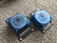
Talema/Nuvotem/Amveco (all the same) PCB mount toroids are adequate, affordable, 100% silent and ...available off the shelf in the most used voltages. Way better with regards to stray field, hum etc. compared to EI types certainly in small devices like DACs and preamps. Recommended as a simply good choice. The ones on the picture are custom types with 4 output voltages found on Ebay.
On the other hand hand is supporting local craftsmen a good choice when one is prepared to pay the often higher price. Knowledge is otherwise seeping away.....
Last edited:
They're killing us with the postage. Not only JLC, but others too.
I had that transformer for testing, some cheap 5VA 15V+15V, but it is not from ebay. I took the torus 10VA.
We ruined a man's theme. 🙄
I had that transformer for testing, some cheap 5VA 15V+15V, but it is not from ebay. I took the torus 10VA.
We ruined a man's theme. 🙄
Oops, true but I hope the question was already answered.
Those toroids are custom wound and usable to have various DC voltages and therefor reduce heat/losses. The normal ones have 2 secondary windings. Anyway, when choising toroids better choose a molded/dipped one. Besides that the chassis mount lead wire versions in below 15VA size are nowhere to be found anymore. Still found on websites and in catalogues but please try to order one. The 3.2, 5 and 7VA types were practical. Easy on the switches and easier to filter out RF/garbage coming via mains.
Those toroids are custom wound and usable to have various DC voltages and therefor reduce heat/losses. The normal ones have 2 secondary windings. Anyway, when choising toroids better choose a molded/dipped one. Besides that the chassis mount lead wire versions in below 15VA size are nowhere to be found anymore. Still found on websites and in catalogues but please try to order one. The 3.2, 5 and 7VA types were practical. Easy on the switches and easier to filter out RF/garbage coming via mains.
Last edited:
- Home
- Source & Line
- Analog Line Level
- LM4562 max safe current
