Just for fun exercise here decided to run the schematics in the simulator.
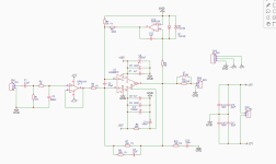
Original Cordell's schematics is attached:

Here is the TI application note schematics for the servo:

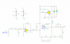
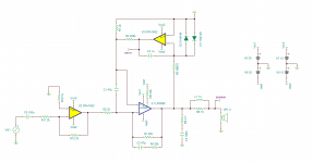
And here is my take on it - drafted in TINA TI simulator:

It is almost the exact copy of the one from the TI application note. Super gain clone has its phase reversed back and so the LM3886 outputs the signal with the same phase it was fed to the input of the first opamp. I did not bother with that additional step in my schematics. It allowed to save on one additional opamp. I am using OPA2134 as I personally listened to it and I like the sound a lot. It also has ah-ok DC precision to work as a servo. Loading OPA2134 with easier load (2K in my case) should produce less distortion - according to the graph in the datasheet.
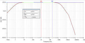
Servo values got adjusted to give difference of 47dB at 20Hz - that is between usable signal and the feedback one:

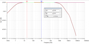
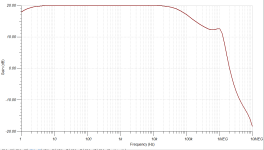
Frequency response is -0.03 dB at 20Hz and -0.11 dB at 20KHz. That is with the gain of 20dB:

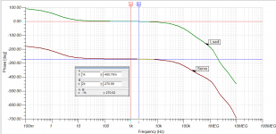
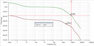
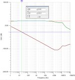
Stability components were added to the schematics to insure proper performance of the LM3886. As far as I understand opamp stability theory - idea is to make sure we are avoiding oscillation condition where the output signal phase is inverted 180 degrees and fed back to the inverting input of the LM3886. With given values for stability components phase is preserved under 180 degrees shift up to 934 KHz and depicted in the graph below:

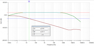
Comparing that result to the open loop gain graph for LM3886:

At the end I just wanted to mention that I am not an expert in the field and could have made mistakes - therefore I would really appreciate any input on any part of this analysis.
Attached is the zip file with simulation.
Original Cordell's schematics is attached:
Here is the TI application note schematics for the servo:
And here is my take on it - drafted in TINA TI simulator:
It is almost the exact copy of the one from the TI application note. Super gain clone has its phase reversed back and so the LM3886 outputs the signal with the same phase it was fed to the input of the first opamp. I did not bother with that additional step in my schematics. It allowed to save on one additional opamp. I am using OPA2134 as I personally listened to it and I like the sound a lot. It also has ah-ok DC precision to work as a servo. Loading OPA2134 with easier load (2K in my case) should produce less distortion - according to the graph in the datasheet.
Servo values got adjusted to give difference of 47dB at 20Hz - that is between usable signal and the feedback one:
Frequency response is -0.03 dB at 20Hz and -0.11 dB at 20KHz. That is with the gain of 20dB:
Stability components were added to the schematics to insure proper performance of the LM3886. As far as I understand opamp stability theory - idea is to make sure we are avoiding oscillation condition where the output signal phase is inverted 180 degrees and fed back to the inverting input of the LM3886. With given values for stability components phase is preserved under 180 degrees shift up to 934 KHz and depicted in the graph below:
Comparing that result to the open loop gain graph for LM3886:
At the end I just wanted to mention that I am not an expert in the field and could have made mistakes - therefore I would really appreciate any input on any part of this analysis.
Attached is the zip file with simulation.
Attachments
Last edited:

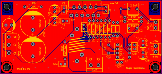
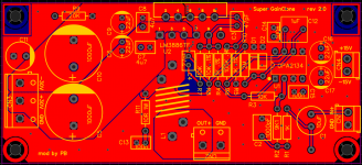
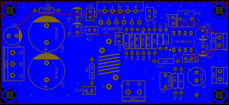
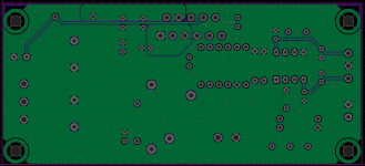
Gereber design for the schematics if someone is interested to build this is attached below:
Attachments
Last edited:
Preserving phase simulation results and schematics are attached.
Attachments

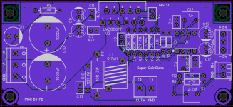
PCB board is attached with this post.
Input capacitor is Nichicon UFG can be found on Mouser - 647-UFG1K100MEM1TD
1000pF capacitor is film type - Mouser # - 871-B32529C102J
Input capacitor is Nichicon UFG can be found on Mouser - 647-UFG1K100MEM1TD
1000pF capacitor is film type - Mouser # - 871-B32529C102J
Attachments

Last edited:
You would do well to follow TI/Nat Semi's advice and value the bypass caps as specified -- 100nF and 10uF
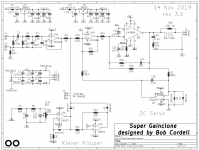
Here's Bob's Super Gain Clone, including his Klever Klipper, as implemented on diyAudio in a Group Buy, Dec 2019. End-to-end it's noninverting. (thread link)
_
_
Attachments
I just followed advice from this article - https://neurochrome.com/pages/supply-decouplingYou would do well to follow TI/Nat Semi's advice and value the bypass caps as specified -- 100nF and 10uF
Here's Bob's Super Gain Clone, including his Klever Klipper, as implemented on diyAudio in a Group Buy, Dec 2019. End-to-end it's noninverting. (thread link)
_
Thanks for linking the thread. It is really nice one to one schematics. I guess I'm just having fun trying to come up with different varieties of the same idea - using LM3886 as inverted to reduce common mode distortion.
You can see a comparison between the LM3886, LM3886 Super GainClone, and LM3886 Super GainClone with Klever Klipper here: https://neurochrome.com/pages/super-gainclone-with-klever-klipper
Tom
Tom
Simulation does not normally model power supply decoupling.You would do well to follow TI/Nat Semi's advice and value the bypass caps as specified -- 100nF and 10uF
Simulation with the LM3886 model included with TINA-TI doesn't model anything power supply related. Not even the load current is reflected in the supply current.
Tom
Tom
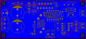
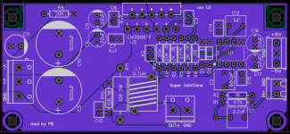
Another revision of the PCB - reorganized few things on the board.
Attached is also TINA-TI simulation file (zipped).
Attached is also TINA-TI simulation file (zipped).
Attachments


Well...from that link I understand your modulus 86 is superior, but your modulus 86 schematic is not publicly available...I'm the cheap guy here so I take the only usable advice that the bare lm3886 is good enough compared with the SGC ...at the moment I can't afford even buying half of one modulus 86 from overseas so I have to stick with giving my ton of electronic components a meaningful use...Funily enough I built two lm3886 amps and never used them at least for a second to drive a speaker...I used them in a sine VFD (46...81hz ) for a turntable motor...You can see a comparison between the LM3886, LM3886 Super GainClone, and LM3886 Super GainClone with Klever Klipper here: https://neurochrome.com/pages/super-gainclone-with-klever-klipper
Tom
That's no surprise. The Modulus-86 has built-in error correction that drives the distortion into the abyss and improves a range of other variables as well. It's a composite amplifier and not the only composite LM3886 amp on the block, so there are options if you don't want to pay someone to provide a circuit that works well out of the box.Well...from that link I understand your modulus 86 is superior, but your modulus 86 schematic is not publicly available...
I don't think that's the only usable advice, but your conclusion holds up if you're on the cheap. If you'd like to spend a bit more, I think you're better off putting your money towards a composite LM3886 rather than the Super GainClone.I'm the cheap guy here so I take the only usable advice that the bare lm3886 is good enough compared with the SGC
Tom
So I finished testing of my basic 3 amps. One TDA7294 one Transistor and one basic LM3886.
Of the 3 I like the LM3886.
So Id like to build something nice with it. I have 2 LM3886 ICs left with me.
Im a few months into this new hobby so forgive the noob questions.
What I know I like the LM3886. I would like to have an Op-amp on the same PCB that does some pre-amplification and acts as a buffer. and a power supply on the same board.
It would be nice to run it as a differential amp. All I know about differential amps is that my Akai AMP uses the tech with two STK Ics.
And from basic reading a differential setup does work better.
Some searching and reading I found a site sharing a LM3886 differential schematic. Problem is it has only the LM IC on it. No opamp.
My understanding is to run in differential mode you need two amps. Have no idea what Servo means in this context.
I quite like the latest LM3886 boards out of china. Where one board does everything i.e. speaker protection, two op amps. two LM3886 ICs everything on one board. But problem is my country has blocked aliexpress. We cant buy from them any more. Long story short. Is there a project out there that does everything I need i.e. with opamp, works in differential mode. Stereo setup. Power section. etc.
Is there a project out there that does everything I need i.e. with opamp, works in differential mode. Stereo setup. Power section. etc.
Not aware of one like that. It seems that having separate modules for the amplifier is actually better as you can troubleshoot easier. Also, you can upgrade in the future without changing the whole board. For example, if power supply is a separate board, you can try using linear power supply, or later try SMPS type.
It would be nice to run it as a differential amp. All I know about differential amps is that my Akai AMP uses the tech with two STK Ics.
And from basic reading a differential setup does work better.
Differential signaling is one thing.
Having two LM3886 in a bridge configuration is a different thing.
Differential signal means you have three wires: IN+, IN-, and GND. At some point IN+ and IN- are added together: it can be done by OPAMP before going into LM3886, or LM3886 can add those, or use two LM3886 to add it at the speaker.
- Home
- Amplifiers
- Chip Amps
- LM3886 super gainclone gets simulated in TINA-TI