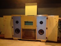
Hello all, need some advice for the following design. Cabinet photo attached.
Build Stages:
Stage One: Three-way speaker install. Each enclosure is 70 litres. Drivers, Tweeter, Mid and Woofer. Single Sub-Woofer (35 litre enclosure). Simple passive cross over powered from existing Mission Amp.
Stage Two: DIGI-FP, VOL-FP and MiniDSP 2x8 (https://www.minidsp.com) acting as a digital cross over feeding set of 8 LM3886 amps using neurochrome.com LM3886 Done Right PCBs (LM3886 Done Right). Running into above drivers.
Stage Three: Build out set of tower 3 ways and sub woofers driven from above audio (speaker patch panel on rear of cabinet)
Design Criteria:
- Will not be driving LM3886 amps hard probably will range 10-20 watts max.
- Selection of music tastes from acoustic guitar, Jazz Lounge and good old heavy metal. Will be using MiniDSP and VOL-FP to set up pre-sets for music style and stage 3 fine-tune towers to the room (90 sqm ‘man cave’)
Questions:
1. Recommended drivers for 3 ways installed in cabinet, and subwoofer (prefer something from PartsExpress.com)
2. Heatsink requirements for 8xLM3886 amps
3. Recommended Power Supply design for 8xLM3886 amps (my current guess is about 50 watts draw per amp)
Thanks in advance.
Malcolm
Attachments
Heat sink, about 1.5x2x.75" with 5 fins or more should be adequate, per IC.
BTW I found a huge quantity of suitable heat sinks in a dead 50" LED television on the curb garbage day last week. Somebody had conveniently pulled the back and foil wrapped the fuses, so it only took me about 15 minutes to pull the power oscillator boards. I found a couple in a projection TV on the curb 3 years ago.
Power transformer, I'd stay 55 vct or below, in case your local line gets above nominal and pushes the voltage bigger than 1.4x nominal. 84 v peak according to the datasheet. You have the right wattage off the datasheet, 50w so I=sqrt(P/R) where R is your speaker impedance. You've said P would be 400 W. With crossovers, the drivers are not paralleled. I is current rating. Not all channels are full power at once possibly, so you may get away with less current rating. The 5 channel TV amps certainly save money in the power transformer, but then I've never been impressed by one of those setups.
Homemade speakers, the ones I have heard my friends build sounded horrible. There is a lot more to flat undistorted speaker performance than putting drivers in a box. Of course men that have fired guns or ridden cycles or ran yard equipment without ear protection can't tell the difference anyway. Ears that will respond to 14 khz like mine are pretty rare over age 12 these days.I always wore ear protection at work and in the military, but I've started wearing ear protection on my bicycle these days, the other vehicles/ambulances/yard equipment are so incredibly loud now.
I've found 2 way horn/15" bar band salvage speakers to be the best available around here, using piano source as a test. See my tag line for what I've bought. Of course the 15" woofers drop off at about 55 hz: Adequate for piano response. There are speaker designs on that sub forum, if you follow the plans exactly correctly you might get something good. Testing in anechoic environment is important IMHO, bits of fluff for damping and sealing integrity are important.
Best of luck.
Last edited:
I generally recommend running the LM3886 on ±28 to ±30 V rails for a general purpose stereo amp. I make this recommendation based on the max guaranteed output current of the LM3886 (7 A). 7 A into 4 Ω -> 28 V. Add a bit for the drop-out across the LM3886 and you get ±30 V rails. Under these conditions, I recommend a heat sink with a thermal resistance of 1.0 - 1.3 K/W per LM3886.
If you want to squeeze out every last watt and run an 8 Ω load, you can increase the supply voltage to ±35 V. Due to mains variation, etc. I would not design for higher than that. The only exception would be if you use a well-regulated supply, such as a switch mode supply. In that case, ±36 V is a good target as many supplies are available with this voltage. With the 8 Ω load, less power is dissipated in the LM3886, so you can get away with a heat sink with a thermal resistance around 1.5 K/W.
Above heat sink thermal resistances are calculated based on a max heat sink temperature of 60 ºC at 25 ºC ambient temperature. Furthermore, they assume that the amplifier is driven by a music signal with a crest factor of 14 dB. For continuous sine wave operation, the heat sinks need to be larger.
Figuring out the thermal resistance of a heat sink is more involved than the dimensions and number of fins. The thickness of the heat spreader between the fins plays in as well. Generally, it is a task that is best left to the manufacturer. Alternatively, you can measure the thermal resistance of the heat sink by dissipating a known amount of power into it and measuring the temperature differential between the heat sink and the ambient air.
If you are interested in the math that led to my recommendations or some links to some heat sink manufacturers so you can survey the heat sink sizes, I suggest having a look at the Thermal Design section of my Taming the LM3886 Chip Amp pages.
I ran a thermal experiment with the LM3886 a while back. You can find the data here: http://www.diyaudio.com/forums/chip-amps/265771-lm3886-thermal-experiment-data-4.html#post4144753
If you are looking to minimize the heat sink size, your best option is to lower the power supply voltage. That'll give you less output power, but also less power dissipation.
Tom
Last edited:
There are a couple of ancillary factors that the DIYer can consider when sizing the heat sink and power supply. Do you anticipate continuous high power operation playing compressed pop music or will the power demand be more moderate (perhaps you have a very efficient set of loudspeakers) and the LM3886's max power is only needed for "peak headroom"? These will for sure influence how much heat, on average, will be generated by the LM3886. Also, if you undersize the transformer, as you draw more (continuous) power the rail voltages will sag somewhat and this can be a hedge against driving the amplifier too hard too long and pushing it into thermal overload.
If you are coming from a commercial standpoint, where you need to design the amplifier to perform under the worst case conditions, and keep performing even under mild abuse, then you will likely have much more strict requirements for heat sinking, power supply capability, and so on. If the DIYer has a specific need, then they can tailor the design if they know that the use will fall within a certain level of power demand, etc.
If you are coming from a commercial standpoint, where you need to design the amplifier to perform under the worst case conditions, and keep performing even under mild abuse, then you will likely have much more strict requirements for heat sinking, power supply capability, and so on. If the DIYer has a specific need, then they can tailor the design if they know that the use will fall within a certain level of power demand, etc.
- Status
- Not open for further replies.