HIFI mono LM3886 power amplifier board / can be connected in parallel | eBay
Anybody tried this one?
I have built a couple of the LM3886 chip with the XY pcb. Use a starground bolted to the chassie to get rid of some hummmmm. There are still a little bit hum, so I think I will build me another amp, with another type of PCB. Perhaps there will be no hum on this PCB?
Anybody tried this one?
I have built a couple of the LM3886 chip with the XY pcb. Use a starground bolted to the chassie to get rid of some hummmmm. There are still a little bit hum, so I think I will build me another amp, with another type of PCB. Perhaps there will be no hum on this PCB?
Connecting chip amps in parallel isn't as straightforward as wiring them up. The amplifiers have to match very closely, and there has to be a resistor in series with each module output.
Matching the amps closely means using precision resistors in critical places like the feedback loop. A batch of 1% resistors can be sorted through to get better than 1% match.
Any mismatch inside the audio passband will translate into higher distortion. For this reason, I think that paralleling Ebay boards is a bad idea. At the very least I would substitute some parts with better ones; especially the feedback resistors.
I prototyped 4xLM1875 in parallel. They were all on the same board and heatsink. I just did it as an exercise but it did work great. Lots of parts but it worked as intended. LM3886 would be trickier, but it's been done. One of our members (Tom) even sells boards he engineered himself.
Also, there's an old TDA chip that's designed to parallel the outputs. They're a little tricky to use (they fry easy if you're not careful) but they're a proven design. I've wondered if you could use a different front end and just use the buffer part of those chips.
Perhaps there will be no hum on this PCB?
Hum is usually due to not parsing your grounds correctly. Star grounds typically cause ground loops if haphazardly applied. I never use them.
You have to keep the grounds separate. All ground branches lead to the power supply PC board, right by the caps. And yes I said branches. Clean branches (like the input grounds) and dirty branches (like on board bypassing and power grounds) must be kept separate. They must only connect at one point! Any deviation and you have hum and distortion.
I did an exercise with one of my designs, the buffered volume control. I typically build this with expensive parts (Alps Blue Velvet volume control, Vishay-Dale CMF series resistors, etc). So I built one with cheap parts (Radio Shack 1/16 watt carbon resistors, $2 generic volume control, 5532 op amps, etc), but with the same careful layout and grounding, same board. It was audibly inferior to the usual one that costs 6 times as much to build, but there was no hum, pops, or excessive noise. It worked perfectly fine and was actually usable. So that demonstrated to me that layout and grounding is most of the battle in audio circuits. And it's free; no fancy parts are necessary. In fact, if you use fancy parts but get the layout and grounding wrong, then you are totally wasting your money and effort.
I´d try to work on what you´ve got before rushing out getting another unkown PCB.
Here´s some nice guidelines from forum-members:
Ground Loops
Maybe it is the PCB, but chances are you can at least improve your setup by a good margin.
Also: do you really need to parallel?
If and only if you should need another PCB, there´s a wealth of really good designs out in this forum.
I got 4 channels of this PCB in the "swap meet" part of the forum:
An open source layout for LM3886?
There´s this Bob Cordell's Super Gain Clone PCB (LM3886) and a stripped-down version: Compact3886
There are many more designs though. Just check the chip amps forum.
There´s also a wealth of information on this site (not only about grounding):
Taming the LM3886 Chip Amplifier: Grounding – Neurochrome
I think we're too fast here!
Nobody asked for a bridged amplifier.
It's not even clear if stenak paralled the boards or not.
There's hum, that's for sure.
Nobody asked for a bridged amplifier.
It's not even clear if stenak paralled the boards or not.
There's hum, that's for sure.
I have built a couple of the LM3886 chip with the XY pcb. Use a starground bolted to the chassie to get rid of some hummmmm. There are still a little bit hum, so I think I will build me another amp, with another type of PCB. Perhaps there will be no hum on this PCB?
Hum if already star grounded is possibly an earthing problem.
1/ 0 earths is bad.
2/ 1 earth is good.
3/ More than one earth in entire system is bad.
I have a amplifier test bed with croc clips for power, input and output. Unless I earth through my scope for testing it hums like mad.
Use a pair of XY pcbs and have a star earth point near the IEC socket. One wire from power supply pcb,one wire from earth on the IEC socket, one wire from the XY amp pcb, and one wire from the minus output. All these wires are connected/bolted to the chassie. But still I have the hum/buzzing in my loudspeakers. Also tried a 100nF capacitor, 10 Ohms resistor, and two diodes connected between chassie earth and PSU earth, but that did not make any difference. I read an article on the internet, somewhere, where there was a discussion about "grounding/earthing" a project where a pair of XY peeceebees were used, but I can not find the article anymore. I like the sound of the LM3886, so that is the reason why I am asking for advice, if the are some other peeceebees out there that are properly built. Thanks a lot for your advice. Appreciate that!!
Hi
if the chassis is anodized, re check if it is scratched to give you a good electrical contact....
did you use this power supply for other amp boards too? It is just an idea to find out if the error goes with the psu /housing or it could be the amp boards...
chris
if the chassis is anodized, re check if it is scratched to give you a good electrical contact....
did you use this power supply for other amp boards too? It is just an idea to find out if the error goes with the psu /housing or it could be the amp boards...
chris
There are som Mods for the XY peeceebees om the internett. I have seen this starground been used before, and probably with a good result. I will check the connection. Thanks to you all.
It sounds as you already digged into the topic of grounding.
More often than not, it helps to make a little sketch of your connections and especially ground.
Does your PCB have a ground plane?
Are the mounting holes grounded and if yes, do you use metal screws?
More often than not, it helps to make a little sketch of your connections and especially ground.
Does your PCB have a ground plane?
Are the mounting holes grounded and if yes, do you use metal screws?
LM 3886 grounding
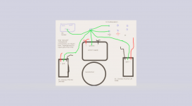
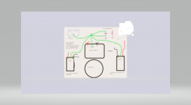
Have not checked the ground connections yet, but here are the drawing around "grounding" my amp. I know that the XY peeceebees are dirt cheap, and that is probably because there are some bad layouts of the ground points on the peeceebee. I have read many articles of how to mod these amps. That is the reason why i was looking for another peeceebees. Maybe the layout are better then on the XY peeceebees? Here is my drawing that shows how the grounding are done.
Have not checked the ground connections yet, but here are the drawing around "grounding" my amp. I know that the XY peeceebees are dirt cheap, and that is probably because there are some bad layouts of the ground points on the peeceebee. I have read many articles of how to mod these amps. That is the reason why i was looking for another peeceebees. Maybe the layout are better then on the XY peeceebees? Here is my drawing that shows how the grounding are done.
Attachments
Hi
Are you sure that the speaker connection + and - are connected to GND !!??
please re check and re draw..
The speakers must be connected to the output of the amplifer. + and -
i personally built a XY 3386 amp and i have no problems. cheap and nice to play around....
chris
Are you sure that the speaker connection + and - are connected to GND !!??
please re check and re draw..
The speakers must be connected to the output of the amplifer. + and -
i personally built a XY 3386 amp and i have no problems. cheap and nice to play around....
chris
Are the input grounds (RCA sockets) connected to the chassis or isolated?
And as said before, the GND of each PCB is isolated from the chassis?
(aka, not connected via screws)
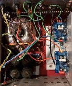
Other than that, maybe your transformer is very near the input cabling or similar? Post a photo if you don´t mind.
And as said before, the GND of each PCB is isolated from the chassis?
(aka, not connected via screws)
Other than that, maybe your transformer is very near the input cabling or similar? Post a photo if you don´t mind.
Ah, always good to see what we´re talking about.
You take the speaker (-) from the star ground not from the PCB, right?
I´d try the speaker-GND from the PCB and then make the output a twisted cable. Also I´d try to move the Thiele network (L//R) closer to the PCB.
It could pick up something from the transformer, the way the cables are lead.
The star ground should ideally also be nearer to the PS-capacitors.
But these are all suggestions from not the most experienced here ;-)
I was lucky enough to never have a humming amp.
- Home
- Amplifiers
- Chip Amps
- LM3886 PCB