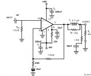
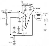
Hi i have a strange issue with my gainclone. Schematic attached here. There is a small noise(need to put my ear on speaker to hear) which is not 50Hz hum or high freq buzz but someting in between bout 1Khz/500Hz. This noise occurs when i connect it to my high pass active crossover.
Connected to another source the gainclone has no issue
Another discrete amp connected to the same active Xover no issue.
Can anyone help. Thanks
Connected to another source the gainclone has no issue
Another discrete amp connected to the same active Xover no issue.
Can anyone help. Thanks
Attachments
Your chance to find a solution will increase, if you post the cross-over schematic as well.
You could compare the values of Ri, Rin, Ci and Cin of the gainclone to the corresponding resistors and capacitors of the other discrete amplifier to start with.
You could compare the values of Ri, Rin, Ci and Cin of the gainclone to the corresponding resistors and capacitors of the other discrete amplifier to start with.
Hi,
the decoupling is not located in the best position.
PIN5 desperately needs decoupling.
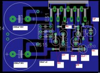
The schematic shows the R+C after the R//L, but the PCB is before.
Try changing the two 10R to 4r7 or maybe even 2r7.
The 22uF in the NFB is too small. Try 47uF.
I cannot see the speaker return.
the decoupling is not located in the best position.
PIN5 desperately needs decoupling.
The schematic shows the R+C after the R//L, but the PCB is before.
Try changing the two 10R to 4r7 or maybe even 2r7.
The 22uF in the NFB is too small. Try 47uF.
I cannot see the speaker return.
Hi andrew thanks for the reply will do the mods you advised. pin 5 is actually connected to the 220uF for the +ve rail. Dou you mean add additional decoupling for pin 5?
There is an error in the schematic for the zobel network its correct on the PCB. (Not in original circuit i've added it.
Speaker return is the green circle next to the caps the other circle is for power ground.
Do you have any other suggestions.
Thanks
There is an error in the schematic for the zobel network its correct on the PCB. (Not in original circuit i've added it.
Speaker return is the green circle next to the caps the other circle is for power ground.
Do you have any other suggestions.
Thanks
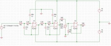
Thanks pacific for your reply i'll add it soon. The input network and feedback of my discreet amp are:-
Cin- 10uF Rin 15K for input
and for feedback Rfeedback=15K Rground=680 and Cground=22uF
Cin- 10uF Rin 15K for input
and for feedback Rfeedback=15K Rground=680 and Cground=22uF
Look at the length of the route from PIN5 to the decoupling cap.
You must have the HF decoupling either on or right next to the supply pins.
Look also at the Zobel return between the decoupling caps. Could they be picking up output pulses and feeding them back into the supply pins? Remember what Walt J. said "all pins are inputs"
Cin=10uF is even worse for allowing voltage to develop across the NFB cap.
Cin must limit the passband so that the PSU and the NFB do not have to handle frequencies at or near their poles.
The other components are also different from the posted schematic.
What are you doing to us?
Put the Zobel on the speaker terminals. I find a 10R 3W + 100nF mylar capacitor work well.
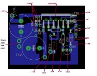
Here is my layout, very similar to yours, except mine is not a true Gainclone as there is only 330uF per rail of capacitance on the board near the chip, with the rest of the capacitance (2x4700uF per rail) is on a seperate board.
For reference, here is the schematic.
Here is my layout, very similar to yours, except mine is not a true Gainclone as there is only 330uF per rail of capacitance on the board near the chip, with the rest of the capacitance (2x4700uF per rail) is on a seperate board.
An externally hosted image should be here but it was not working when we last tested it.
For reference, here is the schematic.
Thanks jaycee, but cannot see your layout can you please attach it thanks.
Since its weekend i've been able to trace the source of the issue. Since it was more quiet around i've been able to listen to my discrete and my gainclone both are dead quiet with any external source but the issue i am having is the cross over itself its the one oscillating. Am not an expert with low level circuit layout but i will post schematic and PCB layout here in case anyone can help. Additional improvements to the gainclone are welcome but like am saying its working well and its not the culprit
Since its weekend i've been able to trace the source of the issue. Since it was more quiet around i've been able to listen to my discrete and my gainclone both are dead quiet with any external source but the issue i am having is the cross over itself its the one oscillating. Am not an expert with low level circuit layout but i will post schematic and PCB layout here in case anyone can help. Additional improvements to the gainclone are welcome but like am saying its working well and its not the culprit
SORRY I WAS WRONG!PLz neglect previous post Gainclone is bad!!!!!!!!!!!!!!!
Sorry guys please neglect the previous post after one last test definitely my gainclone is very bad because using two discrete amps 1 for low pass and 1 for high pass there is no issue. My bad the gainclone is oscillating and making the rest of the circuit oscillate(discrete amp + volume control + active x-over) I'll scrap the the dirty pcb i made and create a new one. Jaycee can you please post back your layout thanks anyone else has a good pcb layout for a LM3886 gainclone thanks. I'll modify my circuit too with respect to your schematic jaycee.
Sorry guys please neglect the previous post after one last test definitely my gainclone is very bad because using two discrete amps 1 for low pass and 1 for high pass there is no issue. My bad the gainclone is oscillating and making the rest of the circuit oscillate(discrete amp + volume control + active x-over) I'll scrap the the dirty pcb i made and create a new one. Jaycee can you please post back your layout thanks anyone else has a good pcb layout for a LM3886 gainclone thanks. I'll modify my circuit too with respect to your schematic jaycee.
Checking the schematic and board i saw the mistake i did, i connected the Gnd pin of the ic to signal ground should have been at power ground. Thanks again
Hi Z,
you are missing an output Zobel and an input RF filter.
In my opinion the 1uF and 22uF are far too small.
you are missing an output Zobel and an input RF filter.
In my opinion the 1uF and 22uF are far too small.
Thanks andrew
Thanks for your reply Andrew the amp will be used as a tweeter amp not full range thats why i kept the caps to 1uF and 22uF. The zobel will be placed at speaker terminals sorry forgot to add this in the schematic. I will add a 470pF caps after the 1k resistor and the other end of the cap to signal ground. Will it be fine?
thanks
- Status
- Not open for further replies.
- Home
- Amplifiers
- Chip Amps
- LM3886 noise issue