Schematics was created by myself utilizing following resources:
Amp board has two LM3886 connected in parallel. Those chips act as a summing amplifier for two differential signals and as a result double the voltage fed into them. For example, if both input differential signals are 2 Vpk each, signal received by LM3886 will be 4 Vpk total. Using two LM3886 in parallel allows to share the current that is fed to the load, and so we can power both safely with 35V and load with 4 ohms speakers.
Circuit was developed and simulated using LTSpice simulator.
Any comments are welcome
- article "The G Word" by Bruno Putzeys - link,
- website - https://neurochrome.com/pages/output-power
- forum post - https://www.diy-hifi-forum.eu/forum/showthread.php?10114-Balanced-Endstufen-mit-Chipamp
- forum post - https://www.diyaudio.com/community/...ed-input-lm3886-design-and-pcb-layout.371161/
- continuation of this thread - https://www.diyaudio.com/community/...llel-with-servo-circuit-build-attempt.383676/
- Pre-amp
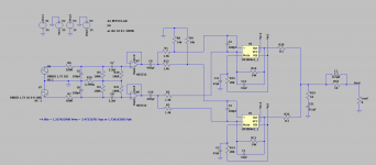
- Main amp board
Amp board has two LM3886 connected in parallel. Those chips act as a summing amplifier for two differential signals and as a result double the voltage fed into them. For example, if both input differential signals are 2 Vpk each, signal received by LM3886 will be 4 Vpk total. Using two LM3886 in parallel allows to share the current that is fed to the load, and so we can power both safely with 35V and load with 4 ohms speakers.
Circuit was developed and simulated using LTSpice simulator.
Any comments are welcome
Attachments
-
 sch.PNG28.2 KB · Views: 327
 -
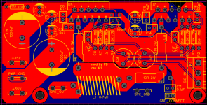
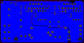
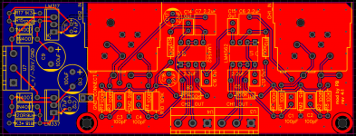 pcb-t.PNG102.9 KB · Views: 301
 -
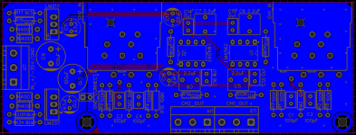
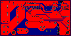
 pcb-t2.PNG63.6 KB · Views: 187
 -
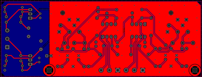
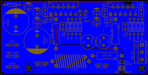
 pcb-b.PNG99 KB · Views: 180
 -
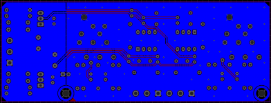 pcb-b2.PNG61 KB · Views: 210
 -
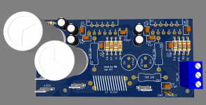
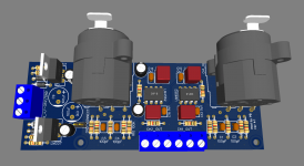 3d.PNG62.6 KB · Views: 260
 -
Gerber_PCB_input-buffer-balanced-r1.1.zip111.2 KB · Views: 113
-
 sch.PNG30.9 KB · Views: 300
 -
 pcb-t.PNG91.4 KB · Views: 271
 -
 pcb-t2.PNG52.2 KB · Views: 182
 -
 pcb-b.PNG84.7 KB · Views: 180
 -
 pcb-b2.PNG45.8 KB · Views: 185
 -
 3d.PNG61.3 KB · Views: 210
 -
Gerber_PCB_lm3886-parallel-amp-board-no-servo-r1.0.zip84.9 KB · Views: 113
-
 sch.PNG21.6 KB · Views: 309
Last edited:

Following YouTube videos helped to understand the theory behind instrumentation amplifier:
- youtube video from TI -
- youtube video from TI -
- youtube video from TI -
- youtube video from TI -
I ended up building something similar but different - https://www.diyaudio.com/community/...uit-build-attempt.383676/page-11#post-7218527Did you ever get these built? I'm curious about the results.
Here is more on the discussion of the above design-
https://www.diyaudio.com/community/...m3886-will-be-in-the-schematics-below.393125/
Last edited: