Hi. I've searched for an answer in this forum, but I can't find one.
On page 21 of the LM3886 datasheet it says,
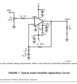
Letting R equal 100 kΩ gives the required input impedance, however, this would eliminate the “volume control” unless an additional input impedance was placed in series with the 10 kΩ potentiometer that is depicted in Figure 1.
I would like to use the volume control, but I don't know where in series the 100k resistor would go. Looking at Figure 1, if placed on top of the pot, it would form a voltage divider and the impedance would be a little under 10k. If placed below the pot, it would raise the impedance, but you could not turn the volume down to zero. The only other place is between the pot and the 1k resistor, but I don't understand if that would change the impedance.
Is this the place they are talking about? If so, how does this figure into the impedance?
Also they say you should not set the input impedance to very high values because of DC offset. But they do not say what value you can use before this starts to happen. Would 220k be too high?
Thanks
Scott
On page 21 of the LM3886 datasheet it says,
Letting R equal 100 kΩ gives the required input impedance, however, this would eliminate the “volume control” unless an additional input impedance was placed in series with the 10 kΩ potentiometer that is depicted in Figure 1.
I would like to use the volume control, but I don't know where in series the 100k resistor would go. Looking at Figure 1, if placed on top of the pot, it would form a voltage divider and the impedance would be a little under 10k. If placed below the pot, it would raise the impedance, but you could not turn the volume down to zero. The only other place is between the pot and the 1k resistor, but I don't understand if that would change the impedance.
Is this the place they are talking about? If so, how does this figure into the impedance?
Also they say you should not set the input impedance to very high values because of DC offset. But they do not say what value you can use before this starts to happen. Would 220k be too high?
Thanks
Scott
Attachments
Use a 100k pot in stead of the 10k. It might help the DC offset to multiply Rf and Ri by 10 also.
Last edited:
If your worried about DC offset, why not throw in a bypass cap on the input?
Why worry about 100K for the input impedance? How much do you need??
I agree with cbdb with the 100K pot, if you must get 100K
Also, this will probably get moved to the chip-amp portion of the site...
Why worry about 100K for the input impedance? How much do you need??
I agree with cbdb with the 100K pot, if you must get 100K
Also, this will probably get moved to the chip-amp portion of the site...
Last edited:
hi, why are you saying this?It might help the DC offset to multiply Rf and Ri by 10 also.
i was convinced that (as a general law, valid for every OpAmp)
- you've to use the lowest R values you can to obtain the lowest DC offset result
- let the input pins see the same impedance (at 0Hz, DC)
- tie down to ground both the inputs (don't leave them floating)
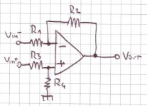
so, in a typical circuit like this (sorry for my Poorman Orcad 😀) :
let (R1//R2) = (R3//R4) you can simplify in R1=R3 and R2=R4
Optionally, use a Cap in series with R1 to obtain DC Unity Gain, and another Cap on the output to completely block DC output..
i'm not sure about what i wrote 😀
Attachments
I was not sure if this should be in solid state or chip amp forum.
So no one knows what they are talking about with the 100k resistor in series with the pot?
I have a 2k source that is too hot for the input of the chip. So I have a 220k resistor parallel with the 10k pot to form a voltage divider to bring the signal down. With the pot turn all the way up, the impedance of the divider is 9.5k. That is good for the chip but a little low for the source. With the pot turned down to say 1, the divider is at .9k. That is too low for the source. It does not sound good until the pot is turn up to about 2 to 3 which would be about 2-3k.
I would like to adjust the value of the pot/divider to better match the source at low volumes. That is why I am trying to figure out what the impedance limits are and how much I can raise the impedance.
Thanks
You seem to be confused about parallel and series connection. If you get values between 0k9 and 9k5, the 220k resistor is obviously in parallel with the potentiometer. In a series connection you would get 230k.
..110k, and your volume would be limited to about 9% of what you have now.
Exactly. The impedance would also be 110k, but you could only adjust the volume between ~91% and 100% of what you have now.
The input impedance of your amplifier should be at least ten times higher than the source's output impedance. Replace the potentiometer with a 20k or higher, remove the 220k resistor and forget about the 100k as well.
The reason, why a 100k Rin would reduce DC offset is, that they use a 100k Rf in their example and you explained yourself that they should have the same size.
I would like to use the volume control, but I don't know where in series the 100k resistor would go. Looking at Figure 1, if placed on top of the pot, it would form a voltage divider and the impedance would be
..110k, and your volume would be limited to about 9% of what you have now.
If placed below the pot, it would raise the impedance, but you could not turn the volume down to zero.
Exactly. The impedance would also be 110k, but you could only adjust the volume between ~91% and 100% of what you have now.
The input impedance of your amplifier should be at least ten times higher than the source's output impedance. Replace the potentiometer with a 20k or higher, remove the 220k resistor and forget about the 100k as well.
The reason, why a 100k Rin would reduce DC offset is, that they use a 100k Rf in their example and you explained yourself that they should have the same size.
Last edited:
Yes I do get confused sometimes when trying to put thoughts into words.
Doing what you said with the 20k or higher pot would work great if I did not have such a hot signal.
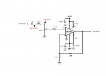
In the first picture it shows that the 2k source is sending a 215V signal. I need the voltage divider to drop that down to a usable level, which is 10V with the 220k resistor and 10k pot.
The second picture shows what I am thinking of doing. I raised the pot value to 25k and the resistor value to 250k. That is a drop of 10 and gives me a signal of 21.5V. I then lower the gain of the chip from 20 to 10. That should give me close to the same output as the first circuit picture but gives me a better impedance load for the source. (So the source sees a 22.7k load at full volume) Then I looked at Figure 2 in the datasheet and saw they put a capacitor after the pot and then a resistor to ground to set the input impedance. Since the pot/divider would become the source the chip sees, (22.7k) I need the input to be 10 times that which I think 220k would be good. So I put a 220k resistor to ground after the cap. The red resistor values are what I was thinking of putting in there, but the values they use in Figure 2 with what I think is 122k impedance are the same as they use in Figure 1 with a 10k pot. So I am not sure if they would be needed to be changed.
Does this seem right?
Also I was looking at the Overture design guide and with the voltage I am using, +-25V, it has a field, Voltage Headroom, that says 17V. Is that the limit of input signal I can feed it before it starts to clip? If so my 21.5V signal would clip at full volume, correct?
Thanks for the responses.
Scott
Doing what you said with the 20k or higher pot would work great if I did not have such a hot signal.
In the first picture it shows that the 2k source is sending a 215V signal. I need the voltage divider to drop that down to a usable level, which is 10V with the 220k resistor and 10k pot.
The second picture shows what I am thinking of doing. I raised the pot value to 25k and the resistor value to 250k. That is a drop of 10 and gives me a signal of 21.5V. I then lower the gain of the chip from 20 to 10. That should give me close to the same output as the first circuit picture but gives me a better impedance load for the source. (So the source sees a 22.7k load at full volume) Then I looked at Figure 2 in the datasheet and saw they put a capacitor after the pot and then a resistor to ground to set the input impedance. Since the pot/divider would become the source the chip sees, (22.7k) I need the input to be 10 times that which I think 220k would be good. So I put a 220k resistor to ground after the cap. The red resistor values are what I was thinking of putting in there, but the values they use in Figure 2 with what I think is 122k impedance are the same as they use in Figure 1 with a 10k pot. So I am not sure if they would be needed to be changed.
Does this seem right?
Also I was looking at the Overture design guide and with the voltage I am using, +-25V, it has a field, Voltage Headroom, that says 17V. Is that the limit of input signal I can feed it before it starts to clip? If so my 21.5V signal would clip at full volume, correct?
Thanks for the responses.
Scott
Attachments

Yes. It is a hybrid experiment. It sounds good once the volume is turned up past around 2 to 3. I'm trying to get it to sound good at the lowest volumes, which I think is because of impedance issues. That is why I am trying to figure out the input impedance limits of the LM3886.
If you put a fixed resistor between the tube and the potentiometer, you don't need to include that into your calculations, because the input impedance is determined by the impedance between the potentiometer wiper and ground. Keep the potentiometer and gain settings as they are and use a series resistor that brings the input voltage to the correct level. Check the resistor's voltage rating, and make sure that the resistor has sufficient power rating. E. g. your 220 k resistor would have to dissipate ~0,21 W when 215 V are applied, so you should at least use a 0,5 W resistor there.
hi, why are you saying this?
i was convinced that (as a general law, valid for every OpAmp)
- you've to use the lowest R values you can to obtain the lowest DC offset result
- let the input pins see the same impedance (at 0Hz, DC)
- tie down to ground both the inputs (don't leave them floating)
so, in a typical circuit like this (sorry for my Poorman Orcad 😀) :

let (R1//R2) = (R3//R4) you can simplify in R1=R3 and R2=R4
Optionally, use a Cap in series with R1 to obtain DC Unity Gain, and another Cap on the output to completely block DC output..
i'm not sure about what i wrote 😀
You are correct and we are saying the same thing. DC offset is caused mainly by 2 things, input device mismatches and input bias voltage (IR losses thru the resistors attached to to the inputs) mismatches. The second depends on the input bias current and ressistance. To minimize this you need low bias current (fets help), low bias current mismatch (depends on the devices), and low matched R from inputs to ground (R1||R2 = R3||R4)
Using the cap dosnt stop the need for an input bias current, which must flow thru a resistor which pulls the voltage away from zero.
- Status
- Not open for further replies.
- Home
- Amplifiers
- Solid State
- LM3886 100k input