I plan to build a gainclone, but i want to use SMD as much as possible. ( just for fun and learning soldering at the same time, nothing else )
I have both caps and resistors as 0805, but i wonder if thats enough ?
Do i need some 3 or 5W resistor as anywhere except the one on the output ?
Ahh, it's a LM3875, but that's already in the header.
I have both caps and resistors as 0805, but i wonder if thats enough ?
Do i need some 3 or 5W resistor as anywhere except the one on the output ?
Ahh, it's a LM3875, but that's already in the header.
Attachments
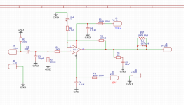
In the schematic you show, R4 needs to be around 2-3W and R7 needs to be 5W. Both can be SMD, but 5W is quite a lot for a surface-mount resistor. Use multiple resistors in parallel or go through-hole for these two depending on what fits you preferences and the PCB layout.
Oh, and I don't know where you have that schematic from but check it against a known schematic: C5 is at least not the right value - should probably be 220nF or thereabouts.
Oh, and I don't know where you have that schematic from but check it against a known schematic: C5 is at least not the right value - should probably be 220nF or thereabouts.

Ahh, thanks.
I got the schema from here: https://www.eleccircuit.com/gain-clone-40w40w-power-amplifiers-using-lm3875/
Yes, it's a typo from me, it should be 0.22uF
AND R5 are NOT connected to Vin, i fixed that now.
I got the schema from here: https://www.eleccircuit.com/gain-clone-40w40w-power-amplifiers-using-lm3875/
Yes, it's a typo from me, it should be 0.22uF
AND R5 are NOT connected to Vin, i fixed that now.
The feedback resistor, R5, is currently connected to the power supply. That's probably not what you want.
I'd use something other than spade connectors for the input, but that's me. I generally hate spade connectors. They're easy to connect but impossible to disconnect. But each to their own. 🙂
C5 should be 100-220 nF. Not 22 uF. It can be an X5R, X7R, X8R type ceramic.
Small, aircore, RF SMD inductors tend to be so small that the magnetic field in them gets excessive near the maximum output power of your amp. Larger ones aren't available, because they're not intended to carry significant current. So that generally pushes you into the inductors with ferrite or iron core. They tend to add distortion.
I don't know the LM3875 as well as I know the LM3886, but I'm thinking you'll want much more than 100 nF for the decoupling. I'd recommend the same as I do for the LM3886: https://neurochrome.com/pages/supply-decoupling
You'll also want at least 470 uF of bulk capacitance per rail. I go with 1000 uF because that value is generally more available and often times actually lower cost than 470 uF.
Note that ceramic capacitors (except NP0/C0G) have a pretty horrid voltage coefficient. Thus, I recommend using X5R, X7R, X8R dielectric for the decoupling capacitors. Even then, you'll want types rated for at least 50 V. If you use 1.0 uF, 50 V types and run ±25 V on the supply, you'll likely get around 350-400 nF of capacitance from those caps. See the capacitor data sheet for details.
I'd scrap the rail fuses. They won't protect the LM3875 or the speakers. The LM3875 is pretty rugged and has internal protection circuits anyway. Also, if one rail fuse blows but the other doesn't, the LM3875 will output DC on the speaker, so you may actually have a scenario where a nuisance blow of the fuse blows your speaker.
If you have reasonably good eyesight or a good pair of reading glasses, 0805 should be no problem to hand solder. But you could take the plunge and buy a toaster oven and a thermometer. Set up a reflow system. It doesn't have to be complicated. I just monitor the temperature and unplug/plug in the oven at strategic points when I solder up prototypes. If you order your boards from outfits like PCB Way you can get the solder paste stencil for an additional $10. It's so satisfying to pop the board in the toaster oven and five minutes later have a fully soldered board. Just don't use the oven for toast after.
Tom
I'd use something other than spade connectors for the input, but that's me. I generally hate spade connectors. They're easy to connect but impossible to disconnect. But each to their own. 🙂
Actually R7 can be 2-3 W as well. It won't see any power dissipation unless the amp oscillates, which it shouldn't if properly designed.R4 needs to be around 2-3W and R7 needs to be 5W.
C5 should be 100-220 nF. Not 22 uF. It can be an X5R, X7R, X8R type ceramic.
Most likely not a good candidate, unless you're designing for a specific harmonic signature. You may be able to find an inductor used in a Class D amp that works, but they tend to be pretty pricey. This is what you need: https://neurochrome.com/collections/chassis-parts/products/output-inductor You can wind your own too.1uH 4.5A 14mohm SMD 6x6mm
Small, aircore, RF SMD inductors tend to be so small that the magnetic field in them gets excessive near the maximum output power of your amp. Larger ones aren't available, because they're not intended to carry significant current. So that generally pushes you into the inductors with ferrite or iron core. They tend to add distortion.
I don't know the LM3875 as well as I know the LM3886, but I'm thinking you'll want much more than 100 nF for the decoupling. I'd recommend the same as I do for the LM3886: https://neurochrome.com/pages/supply-decoupling
You'll also want at least 470 uF of bulk capacitance per rail. I go with 1000 uF because that value is generally more available and often times actually lower cost than 470 uF.
Note that ceramic capacitors (except NP0/C0G) have a pretty horrid voltage coefficient. Thus, I recommend using X5R, X7R, X8R dielectric for the decoupling capacitors. Even then, you'll want types rated for at least 50 V. If you use 1.0 uF, 50 V types and run ±25 V on the supply, you'll likely get around 350-400 nF of capacitance from those caps. See the capacitor data sheet for details.
I'd scrap the rail fuses. They won't protect the LM3875 or the speakers. The LM3875 is pretty rugged and has internal protection circuits anyway. Also, if one rail fuse blows but the other doesn't, the LM3875 will output DC on the speaker, so you may actually have a scenario where a nuisance blow of the fuse blows your speaker.
If you have reasonably good eyesight or a good pair of reading glasses, 0805 should be no problem to hand solder. But you could take the plunge and buy a toaster oven and a thermometer. Set up a reflow system. It doesn't have to be complicated. I just monitor the temperature and unplug/plug in the oven at strategic points when I solder up prototypes. If you order your boards from outfits like PCB Way you can get the solder paste stencil for an additional $10. It's so satisfying to pop the board in the toaster oven and five minutes later have a fully soldered board. Just don't use the oven for toast after.
Tom
BTW, if you're looking for R1 to balance out the input offset current, you'll want R1 = 120k || 4.7k = 4.52 kΩ. You could also set R1 = 0 Ω for lower noise.
Tom
Tom