Hi guys,
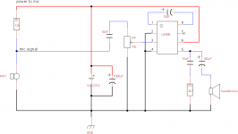
I want to make a simple microphone amplifier using the LM386 chip which I order from ebay. it came with all external components and I hooked it up as shown in the first picture. I am using a 12V power supply and a standard computer headset for microphone (input) and headphones (output).
The circuit I have works well, but I want to add another microphone to the setup. So that the signal of the two microphones is combined into one signal, which is then amplified, and volume controlled by the single potmeter. I've made another image showing what I would like to achieve, but I need some help filling in the parts with the question marks.
I have searched for some simple mixing circuits, but I can't seem to get it to work with my setup. Note that sound quality is not an issue for me, I just want to be able to combine speech from two microphones into one headphone output. If at all possible with the fewest additional parts.
Sorry if this is an obvious question, but I'm a bit of a n00b when it comes to audio/electronics.
Thanks for your help.
Attachments
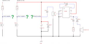
You need to put an inverting mixer before your circuit. Or you could use the noninverting input of the 386 as the input and configure it as a mixer circuit, but it would surely have to be buffered if it was going to be driven by a microphone.
Your circuit is very parsimonious, and adding a second microphone input is going to complicate it a lot. Inverting amplifiers are limited to lower input impedances usually, so even this might have to be buffered.
Consider finding a microphone mixer circuit and putting it in front of your circuit. Elliott Sound Products might have a circuit for you. Remember that any circuit you choose must be single ended if you intend to run it off of 12 volts.
comment
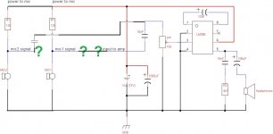
You do not need an inverting summing amplifier to accomplish mixing.
The attached figure shows your two microphones, each with bias current through a 12K resistor. Each microphone has its own coupling capacitor (both 10nF) so that the DC operating voltage can be slightly different for each microphone (this will ensure that they have approximately the same bias current).
The signals are mixed by a direct connection (after the coupling capacitor). A separate mixing stage is not needed. Explanation: If you have two operational amplifier outputs, connecting them directly together is not good. In that case, the op-amp outputs are at different voltages (since they are driven by different signals). Connecting the two outputs directly together means that one output terminal (node) is shared by the two op-amps. This will prevent each op-amp from being in full control of the voltage at its output terminal, since the single node cannot be at two different voltages.
In this situation, some mixer is needed. A simple mixer could be implemented with two resistors, one in series with each output.
But in your circuit, the microphone elements provide _currents_ at their output terminals, and the voltage across each microphone is simply the result of that current flowing through a 12K resistor. Connecting the two microphone outputs together will cause the current from one microphone to flow through a resistance of 6k ohms (that's two 12k in parallel), so the signal voltage due to one microphone will be 6 dB less (that's one-half what it would be if implemented as a single microphone). I assume that you can compensate for this loss with the single volume control pot. Whenever two ground-referenced voltages are mixed, such loss occurs (but it can be made up with active circuitry like an op-amp mixer). Anyway, each microphone does not try to force its output terminal to a particular voltage (like an op-amp does), that is why you can connect them directly together.
I would not connect the microphones directly together without the capacitors, however, because the DC bias points should not be forced to be the same.
Having said all that, you certainly could build fancier circuits using mixers that have volume controls for each microphone. I am just suggesting a very simple extension of what you now have.
Tom
Attachments
Thanks very much Tom, this was the kind of solution I was looking for, for now. I got it to work on a breadboard, the next step is to make it nice and tidy and solder everything together.
Also thanks for not just giving an answer, but taking the time to explain it. it's very helpful!
Also thanks for not just giving an answer, but taking the time to explain it. it's very helpful!
- Status
- Not open for further replies.