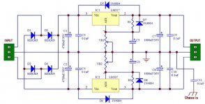
I have a couple of questions about the LM317/337 schematic below that I found on eBay.
1) Are the large HER303 3A diodes really needed for operation below say 200-330mA or will 2A MUR220s work just as well?
2) The circuit shows 1KuF caps(C7 and C8) near the outputs.
Typically, I see much smaller values used in these locations.
Will the 1KuF caps cause any type of ringing or other issues vs. using 100uF or 220uf caps?
Thank you!
Attachments
I don't find putting big output caps on LM317s makes any improvement in SQ, often makes it worse. Perhaps due to reduced stability of the reg - though that depends on the ESR of the cap to a large degree. I think TNT audio had a plot of inducing a resonance at HF by having a too-large output cap. I use large output caps but only after an inductor for HF isolation.
If I were using this circuit myself I'd include RC filtering at the input to the regs as their performance at HF is very lack-lustre. On the diodes, no you don't need 3A types.
If I were using this circuit myself I'd include RC filtering at the input to the regs as their performance at HF is very lack-lustre. On the diodes, no you don't need 3A types.
Putting large caps directly on the output of a regulator is daft for two reasons:
1. other things being equal, the caps will have most effect in exactly the same frequency range where the regulator has most effect - so you are 'solving' a non-existent problem;
2. other things are not equal, most regs have an inductive output impedance so you are encouraging a resonance which will raise output impedance and noise - which is generally the opposite of the reason you had a reg.
If you insist on ignoring the reg datasheet then at least make sure you use a high ESR cap so it does little harm.
1N4002 are adequate for an amp or so. Throw away C7 and C8, they are of no use and will stop the LM regulators regulating correctly due to lag in the response. C5 and C6 should be no higher in value than 100nF, preferable don't use them as the feedback for the regulator will not respond properly and it may oscillate and become unstable.
Look and read the data sheets!
Look and read the data sheets!
Throwing C7 and C8 may be a bit too drastic. The remaining 0.1uF mag be too low for stability. A few dozen uF would probably be a good idea.
Jan
Jan
1N4002 are adequate for an amp or so. Throw away C7 and C8, they are of no use and will stop the LM regulators regulating correctly due to lag in the response. C5 and C6 should be no higher in value than 100nF, preferable don't use them as the feedback for the regulator will not respond properly and it may oscillate and become unstable.
Look and read the data sheets!
I did look at the datasheets, but they didn't coincide with the above schematic.
Datasheet applications are usually a safe guide to using a particular device but not necessarily the best application.
That's why I'm looking for suggestions from people here who have actually used these regulators and may have experimented with different value caps after the regulators.
As for diodes, I have lots of Motorola 1N4004s so I'll use them.
I'm not going to "throw away" C7 and C8 since even the datasheet shows to use a value as low as 1uF.
I'll use 22uF or 33uF, as suggested by jan, instead of 1KuF.
Per your suggestion, I will leave C5 and C6 off the board.
By the way, are C9 and C10 really needed?
C9 and C10 can upset the stability, especially if they are very low loss. I'd chuck them and instead put them close to the load, they will help there.
Jan
Did anyone actually find anything about required ESR values for the LM317 in a datasheet and if so, from what brand? I only see some comments about tantalum and aluminium electrolytics, but no warning that anything goes wrong with ceramic or foil capacitors. For large value electrolytics, I only see warnings that a protection diode across the regulator may be needed, not that it provokes oscillations. Does anyone have experience with oscillating LM317s? Old types of low-dropout regulators usually have an allowable capacitance versus ESR graph in their datasheet, but fortunately the LM317 is a high-dropout regulator.
By the way, it is a different story for the LM337. The LM337 requires a 10 uF output capacitor if you use an aluminium electrolytic. OnSemi explicitly warns against low-ESR capacitors for the LM337, see http://www.onsemi.com/pub_link/Collateral/LM337-D.PDF
By the way, it is a different story for the LM337. The LM337 requires a 10 uF output capacitor if you use an aluminium electrolytic. OnSemi explicitly warns against low-ESR capacitors for the LM337, see http://www.onsemi.com/pub_link/Collateral/LM337-D.PDF
Last edited:
I just found this link:
https://e2e.ti.com/support/power_management/linear_regulators/f/321/t/135490
Apparently the LM317 works fine even with a 10 uF X5R ceramic output capacitor (unlike the LM337).
https://e2e.ti.com/support/power_management/linear_regulators/f/321/t/135490
Apparently the LM317 works fine even with a 10 uF X5R ceramic output capacitor (unlike the LM337).
Does anyone have experience with oscillating LM317s?
Yes but almost all have been when using it as current source, not as voltage reg.
By the way, it is a different story for the LM337. The LM337 requires a 10 uF output capacitor if you use an aluminium electrolytic. OnSemi explicitly warns against low-ESR capacitors for the LM337, see http://www.onsemi.com/pub_link/Collateral/LM337-D.PDF
Well...so much for using Panasonic FC or FMs with these regulators. I assume it's still safe to use them before the rectifier diodes?
Does anyone which Panasonic or Nichicon series would have high enough ESR so as to not cause stability issues with these LM-series regs.?
Did anyone actually find anything about required ESR values for the LM317 in a datasheet and if so, from what brand? I only see some comments about tantalum and aluminium electrolytics, but no warning that anything goes wrong with ceramic or foil capacitors. For large value electrolytics, I only see warnings that a protection diode across the regulator may be needed, not that it provokes oscillations. Does anyone have experience with oscillating LM317s? Old types of low-dropout regulators usually have an allowable capacitance versus ESR graph in their datasheet, but fortunately the LM317 is a high-dropout regulator.
By the way, it is a different story for the LM337. The LM337 requires a 10 uF output capacitor if you use an aluminium electrolytic. OnSemi explicitly warns against low-ESR capacitors for the LM337, see http://www.onsemi.com/pub_link/Collateral/LM337-D.PDF
Marcel, as you know of course, the requirement for a non-zero ESR output cap on this type of regs comes from the particular design of the feed back amplifier. As far as I know, the 317 is just a 'normal' 3-pin regulator but with the feed back divider build-out, so I would expect that the requirement is the same. An X5R cap may be lossy enough to stay out of trouble but I would be very careful especially in a series production.
Better safe than sorry!
Jan
The wrong value and type of cap can create problems which fall short of actual oscillation. As I said, you can get a peak in noise and output impedance. Oscillation occurs when this peak reaches up to infinity!
The question which needs to be asked is "what is the output cap supposed to do?". A moderate value cap will take over where the reg leaves off i.e. higher frequencies. Up there the output impedance will be higher and more resistive, as the internal feedback loop will have run out of loop gain. Thus the cap does something useful.
A big cap does almost the same job as a regulator (so why have both?) but with the crucial difference that it adds capacitance whereas the reg adds inductance. Put the two together and you have the potential for resonance problems, just like any LC smoothing circuit.
1Kuf in this post and the first is a nonsense. 1KuF = 1 Kelvin micro Farad..............I'm not going to "throw away" C7 and C8 since even the datasheet shows to use a value as low as 1uF.
I'll use 22uF or 33uF, as suggested by jan, instead of 1KuF..................
You meant to write 1000uF which can be shortened to 1mF (m=milli = 10^-3 multiplier)
I don't agree with all of the above replies. Post8 is correct.
I find that cheap ordinary esr electrolytics on the output are good enough and don't degrade regulation.
I also use ordinary esr electrolytics across the lower resistor (VR1). You already have the protection diode to discharge this and specifically required when a high value electro is used.
C3 & C9 should be close to the reg leadouts. But do not use low ESR film capacitors.
But move your Zero Volts tapping points for the various component connections.
Spreading them out is not the best way to get good performance. Today a revived old Thread shows the correct way to do this.
http://www.diyaudio.com/forums/powe...7-experiments-measurements-7.html#post4294717
The TNT website is also a superb resource
http://www.tnt-audio.com/clinica/regulators_noise1_e.html
http://www.tnt-audio.com/clinica/regulators2_impedance1_e.html
Notice the peaking on some of the arrangements.
Last edited:
For some simulations of the peaking see this post. http://www.diyaudio.com/forums/digital-source/164962-caps-after-regs.html#post2154236
For my own circuit I chose to use a large low ESR cap with a small series resistance added, just enough to ensure no peaking (I think it was around 0.3 ohms). Comparisons with various output caps (in the real circuit) showed that with the large cap I had the lowest noise floor, but I was always sceptical about whether it reduced the ability of the reg to do it's job.
At least one of the LM317 datasheets does mention the ringing that can occur due to the capacitance interacting with the output inductance of the reg, but I don't remember which one. I have read pretty much all of them and different ones have different insights.
Tony.
If you have the regulator output impedance graph, capacitor selection is simple.
Looking at LM337 output impedance graph (fig. 14, with Cadj) gives an inductive 0.25 ohms at 100 kHz, with negligible resistive component (a few mOhms). This corresponds to a 400nH inductor.
Now, we select a cap and ESR which will give a proper damping factor (Eta=1.5 ... 2) with a 400nH inductor.
Eta = R/2*sqrt(C/L)
For C=33µF and ESR=0.5 ohms we get Eta=2.3 which is well damped. For ESR=50 mOhm, then is is strongly underdamped, which is why you don't put polymer, ceramic or film caps at the output of these regs... at least not without adding a larger value, high-esr cap for damping.
Now, without Cadj, the graph gives impedance for Vout=10V, which is 40 mOhm + 4 µH and the same calculation can be done... a 33µF cap with 1 ohm ESR, which corresponds to the type of caps generally available when LM337 was designed, gives an acceptable Eta=1.5.
Please note that this method ignores the reg's second pole and cap ESL. You been warned 😀
Actually I have a circuit with an LM317 of which the output is decoupled with two X5R 10 uF ceramic capacitors, which should be perfectly acceptable according to the TI application engineer I referred to earlier.
I just attached my scope to it and saw a perfect 1.47 kHz sawtooth-shaped oscillation! Connecting a 47 uF aluminium electrolytic capacitor (Philips 037-series) in parallel with the X5R capacitors solved the issue.
I had heard a faint whistle coming out of the circuit sometimes, but I always thought it was one of the switch-mode regulators on an FPGA board in the same circuit. I didn't always hear it, so apparently it was on the edge of oscillating. It seems to be some sort of large-signal oscillation, because just momentarily touching the output with the electrolytic capacitor was also sufficient to get rid of the sawtooth.
By the way, my LM317 is actually a rather old one from ST rather than one from TI.
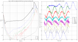
This is an output impedance measurement of LM317 used as 1V2 regulator with one 10µF X7R cap on the output. As you can see from the huge spike in the impedance graph (left, black) it does not work at all 😀
I don't remember which manufacturer this was from.
I don't remember which manufacturer this was from.
Attachments
If anyone wants to play with modeling of LM317 (I don't have a 337 model as I like to do things differently 😉 ) the spice models I made available are here --> http://www.diyaudio.com/forums/powe...ng-lm3x7-regulator-circuit-7.html#post3328300
Tony.
Tony.

- Status
- Not open for further replies.
- Home
- Amplifiers
- Power Supplies
- LM317/337 Schematic Questions.