Hi!
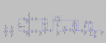
I would like to do a stereo amp with two LM1875 amp, balanced inputs, and use baxandall volume controls before it to have a good volume balance between the two channels with a dual gang pot.
I have come to the schematic in attachement.
What do you think about it please?
Do I need more filtering before the power amp for subsonic and ultrasonic frequency?
Thanks a lot for your help!
Please apologise my poor English.
Attachments
I suggest you ESP project 97 for tone control. Google to know more about it. Good luck!
Last edited:
Thanks nirupambhowmick!
I have already read that project, like a lot of other ESP articles 😉
I don't want to ad tone control, as I would like to keep this simple. What question me is more out of audio spectrum frequencys. Should I cut them more? I am probably overthinking it...
I have already read that project, like a lot of other ESP articles 😉
I don't want to ad tone control, as I would like to keep this simple. What question me is more out of audio spectrum frequencys. Should I cut them more? I am probably overthinking it...
Baxandall is good in my experience.
My only comment would be the diodes to the rails can inject any noise in the rail into the audio path. I would lose them.
My only comment would be the diodes to the rails can inject any noise in the rail into the audio path. I would lose them.
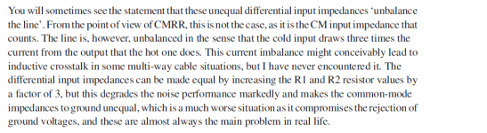
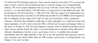
I would also match the input impedance for the balanced input.
For the negative side it's now 20k and for the positive input 6.67k.
https://e2e.ti.com/blogs_/archives/...the-input-impedance-of-a-difference-amplifier
Diodes depends how this circuit is being used.
When long cables are being used it could be handy.
Personal experience with professional equipment, is that the noise isn't very significant.
C6 and C17 seem a bit unnecessary
Also the values for C1 and C4 are a little high 4.7-10uF is big enough.
Depending on the use case I would even take them smaller.
Last edited:
Thanks a lot!
I put his quote about this in attachement.
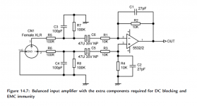
C17 is there to prevent any DC offset to go into the power amp, and so to the speaker after it.
He said the bigger is the better here, so the capacitor doesn't mess with the common mode impedance, due to bad tolerance. He even advice to use 100uF or 220uF if possible. (Quote in attachement too)
Have a nice week end!
I will probably etche the PCB with place for them and try with and without them to see how much change it do.My only comment would be the diodes to the rails can inject any noise in the rail into the audio path. I would lose them.
From Douglas Self, in "Small signal audio design", this should not be a real issue.I would also match the input impedance for the balanced input.
For the negative side it's now 20k and for the positive input 6.67k.
I put his quote about this in attachement.
C6 is to prevent any DC offset difference between U1 and U3 to flow into the pot. Honestly I absolutly don't know if it is really necessary... I am gonna use NE5532.C6 and C17 seem a bit unnecessary
C17 is there to prevent any DC offset to go into the power amp, and so to the speaker after it.
This is based (OK, shamelly copied 🙄 ) on Douglas Self design too (in attachement).Also the values for C1 and C4 are a little high 4.7-10uF is big enough.
Depending on the use case I would even take them smaller.
He said the bigger is the better here, so the capacitor doesn't mess with the common mode impedance, due to bad tolerance. He even advice to use 100uF or 220uF if possible. (Quote in attachement too)
Have a nice week end!