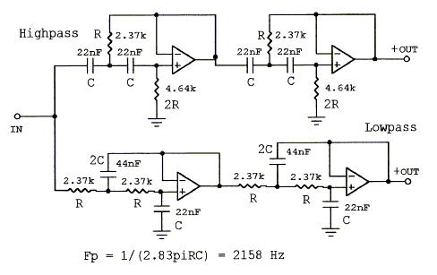
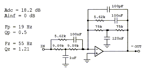
So I did these boards for my own use although I haven't got them made and tested yet. They feature a 12db/octave linkzwitz transform 4th order high/low pass filters all in series with each other. The high/low pass filters use a dual op amp with the same pin configuration as the NE5532. Linkzwitz transform can be any ordinary single op amp.
What I'm thinking is if enough people are interested I will egt these made and get a group buy going? I put this thread in what I thought would be the best place to get views from people that would be interested.
Board size approx. 85mm x 35mm.
Any faults please point them out!
Thanks
Boscoe


I also have a spreadsheet for calculating the values of the filters.
What I'm thinking is if enough people are interested I will egt these made and get a group buy going? I put this thread in what I thought would be the best place to get views from people that would be interested.
Board size approx. 85mm x 35mm.
Any faults please point them out!
Thanks
Boscoe
An externally hosted image should be here but it was not working when we last tested it.


I also have a spreadsheet for calculating the values of the filters.
Last edited:
Hi,
A couple of observations. Depending on the stability of the op-amps you use you may run into problems as you have no HF decoupling on the op-amps. NE5532s are very stable so using them you will probably get away with it. If you are using faster parts you will probably need 100nF decoupling caps close to the power pins on each op-amp. I would advise a separate GND return for these so the decoupling currents do not interact with the signal ground.
I have not checked your filter designs, however for the HF filter multiple feedback filters present less common mode stress on the input stage of the op-amp and hence tend to sound better. (This is also true for the LF but much less noticeable) This is dependant to a certain extend on your choice of op-amp but for NE5532 it is definitely true some of the newer design cope much better with common mode voltages.
Although I have not checked very carefully, it appears the signal goes through the linkwitz transform first then to the HF and LF filters. The linkwitz circuit has many components relatively high gain and quite high impedances which tends to make it noisy. If you only introduce this noise into the LF circuit it will be much less noticeable so I would recommend moving the linkwitz transform to the end of the LF filter. The LF driver will not reproduce the HF component very well. However as this appears to be a two way design you may be able to hear some of it through the midrange. My experience has been the linkwitz transform works best for seal box subwoofers where the noise issues are largely irrelevant.
You only appear to have one set of outputs pads however you have at least two outputs, three if you want pre and post the linkwitz transform. I am not completely sure but it looks like you have fed the output of the LF circuit into the HF circuit.
Another observation which I don't have good evidence for but just anecdotal evidence. Where the signal splits split the ground so that the return currents from the HF and LF filters do not share a common return path.
Also, I think you would get better feed back in the analogue line level section. Once the design is resolved you might want to post a link in this section.
Hope this helps.
Regards,
Andrew
Last edited:
- Status
- Not open for further replies.