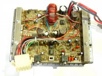
Forgive me if I'm in the wrong forum, I'm a noob here. I'm looking for a schematic for a Linear Power Model 90, not a 901. This amp is not a virgin, somebody has replaced transistors, op-amps and resistors. The same resistor has a different value from one channel to the other. One channel has a MPSA06 and the comparable transistor in the other channel is a 2SC945. I know that's not original. Even a hand drawn schematic would be helpful. I've got it running but it isn't right. Amplitude starts dropping off at about 6 kHz. Any documentation would be helpful.
Thank You.
Thank You.
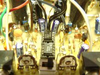
Perry. Thanks for posting. The closeup has a couple of 620 ohm RCA 2% Flameproofs that obviously aren't original and I doubt the value is right. Outputs are TIP101s and TIP106s. There is an op-amp for each channel that should be the same part number. I don't know if the LM4558 is original or the TL072CP. Op-amp outputs on pin 7 also attenuate as I increase the input frequency.
Attachments
I don't have anything close.
The LM4558 is likely OK. In some amps, they used an LM833 at the input and a TL072 later in the circuit. Are you sure that one op-amp is for one channel and the other one for the other channel?
What does the switch do?
The LM4558 is likely OK. In some amps, they used an LM833 at the input and a TL072 later in the circuit. Are you sure that one op-amp is for one channel and the other one for the other channel?
What does the switch do?
Actually I'm not sure that the op-amps drive individual channels. They are dual op-amps so... The switch is for hi or low input impedance. You could use the amp as a booster with the switch in the low Z position.
I've pulled the board and I'm currently flipping it back and forth trying to draw the op-amp circuit. The 620 ohm resistors feed the op-amps from the + and - supply rails. When I remount the sink and power it up I'll see what happens to the op-amp supplies when I increase the frequency. I've never seen an op-amp act like a low pass filter when it's power starved but maybe that's what's going on. Unless there is some feedback being used from a later stage then this problem should be up front. I'll find it.
I've pulled the board and I'm currently flipping it back and forth trying to draw the op-amp circuit. The 620 ohm resistors feed the op-amps from the + and - supply rails. When I remount the sink and power it up I'll see what happens to the op-amp supplies when I increase the frequency. I've never seen an op-amp act like a low pass filter when it's power starved but maybe that's what's going on. Unless there is some feedback being used from a later stage then this problem should be up front. I'll find it.
Perry
The schematic was useful. Thank You. The front ends are different, the Model 90 isn't bridgeable without externally inverting the line-level signal at one of the inputs. This amp is old school. Few people knew anything about bridging amps back in the '70s.
Reading your web pages. Nicely done.
The schematic was useful. Thank You. The front ends are different, the Model 90 isn't bridgeable without externally inverting the line-level signal at one of the inputs. This amp is old school. Few people knew anything about bridging amps back in the '70s.
Reading your web pages. Nicely done.
- Status
- Not open for further replies.
- Home
- General Interest
- Car Audio
- "Linear Power" Model 90