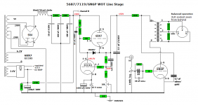
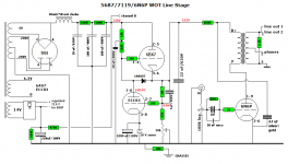
I'm starting to build a line stage preamplifier with output transformers. I'm using a design from Troels Gravesen's website. I'm however not sure if it is possible to have both xlr and phono output. As can be seen in the attached schematics the output transformer have center tap for balanced operation. Can anybody tell me if it's possible to have both xlr and phono output at the same time? And if so do i just connect them parallel?
Attachments
Strictly speaking 'balanced' means 'same impedance on both wires' and 'signal is potential difference between the two wires'. It does not mean 'put half the signal on one wire and inverted half on the other wire'. Therefore you can create a balanced output by grounding one side via a resistor and putting signal on the other, provided you get the impedance right.
However, you cannot simply parallel this with the phono output as this is unbalanced and requires one side to be grounded.
However, you cannot simply parallel this with the phono output as this is unbalanced and requires one side to be grounded.
Requires? I wouldn't say so, no. It would be nice if circuit grounds were halfway well in agreement on both sides, but having an output transformer sure gives you some flexibility. Ever had to deal with any hot chassis sets?However, you cannot simply parallel this with the phono output as this is unbalanced and requires one side to be grounded.
I'd connect the RCA in parallel to XLR pins 2 and 3 and call it a day. (Gain appears to be about 14 dB like this, an OK figure. Only if this still turns out to be too noisy we will have to think about some other options. I would prefer having an input transformer of maybe 1:2 to 1:4 turns ratio and some feedback on the tube to offset the higher internal levels.) Usual convention is pin 2 hot, so I'd inspect the output transformer transformer datasheet again and make sure output polarity is inverted to offset the inverting amplifier topology... not like absolute phase matters much or anything, there's just no reason not to.
Oh, and XLR pin 1 never goes to local circuit ground, it always goes directly to chassis. (The 620Rs remain as-is.)
Last edited:
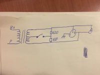
If the CT of the secondary is grounded here, and one end of the winding is grounded at the far end of an unbalanced interconnect from the RCA then you might not get much output. If you want to share the secondary between the two methods then it may have to be left floating, so scrap the two 620R and use a single 1.1k.
Well, yeah, effectively shorting out half the secondary may not be such a good idea after all. I agree - I think I'd just eliminate the center tap ground connection altogether and leave the secondary floating then... definitely no ground loops for one thing.
One could still connect the RCA between center tap and one end to reduce gain if tube noise is a problem... I vaguely remember input noise densities in the order of 40 to 100 nV / sqrt(Hz) as not being atypical, and plus 40 dB (14 dB + 26 dB) that's rather more than I like to see on a hi-fi speaker output.
One could still connect the RCA between center tap and one end to reduce gain if tube noise is a problem... I vaguely remember input noise densities in the order of 40 to 100 nV / sqrt(Hz) as not being atypical, and plus 40 dB (14 dB + 26 dB) that's rather more than I like to see on a hi-fi speaker output.
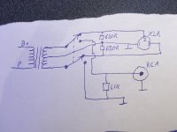
You'd be shorting out the lower half of the output winding in RCA mode. That tends not to be a good idea with transformers.
I'd suggest you do not switch hot / RCA signal, but rather leave those wired in parallel and switch the center tap connection instead (connected in XLR mode, open in RCA mode).
If you should encounter ground loop issues on the output side, you could still float the RCAs by omitting the circuit ground connection, i.e. RCA shield would connect to 1k1 and transformer secondary but not to ground. There is nothing much that could be done about input-side problems, though the 10 ohms between audio ground and chassis (which connects to PE) should help somewhat.
I notice you copied XLR wiring as shown in the schematic - XLR pin 1 should actually not go to regular audio ground, but rather to chassis (case) and nowhere else, ideally with a short wire right at the connector. This is the Right Way(R) of doing it, as per AES48-2005. Otherwise shield currents generated by differences in protective earth potential could travel through XLR pin 1 into the circuit, make their way across internal ground (which has a low but definitely finite resistance) and out via 10 ohms to protective earth. (Imagine it didn't have the 10 ohms - that would mean even more voltage dropped across audio ground.) Doing it properly routes these currents entirely around the circuit, straight into chassis and to protective earth.
BTW, with as much voltage as the regulator is dropping, you could get pretty much the same 100 Hz ripple rejection with just passive filtering (increasing the 100R droppers in value). The result might turn on a bit more slowly and wouldn't look as impressive, of course, but it would save a bunch of heater current. Bit of a silly design, really. Without the regulator it would just be a basic SET line stage.
- Status
- Not open for further replies.
- Home
- Source & Line
- Analog Line Level
- Line stage both balanced and se output