Hello everyone,
I'm new to electronic design so i need your help.
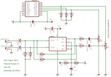
I want to amplify the output of a DAC (TDA1543) in order to feed it after to a power amp and control the volume.
I made some rough calculations and a schematic using an LM4562.
Can you please have a look and give me some comments.
Thank you very much
I'm new to electronic design so i need your help.
I want to amplify the output of a DAC (TDA1543) in order to feed it after to a power amp and control the volume.
I made some rough calculations and a schematic using an LM4562.
Can you please have a look and give me some comments.
Thank you very much
Attachments
hi bluetech
you can use the IVY linestage in stereo configuration, look at the manual
http://www.twistedpearaudio.com/linestages/ivy.aspx
it sounds fantastic with opus dac
you can use the IVY linestage in stereo configuration, look at the manual
http://www.twistedpearaudio.com/linestages/ivy.aspx
it sounds fantastic with opus dac
With a 5 V single supply there will be no 2 V output. The output pp voltage will be less than 2,5 V. That leads to a maximum Ueff of (2,5/2)/SQR(2) = 0,88 V.
You should revise your output filter. The capacitors are much too small and they will form a high-pass filter with the following equipment. That means, the filter frequency depends on the input impedance of the power amp. Change the amp and the filter frequency changes. Not good. Therefore R34 and R36 should be connected between the capacitors and the output connectors.
Then the filter frequency will be 1/(2*PI*R*C). With 100k and 80 pF you get nearly 20 kHz. Everything below that will be attenuated. You don't want that, do you?
Very much the same applies to the input filter. Place a resistor (~ 5*P3 or bigger) to ground after the capacitor. Then calculate the high-pass frequency. For a bandwidth from 50 Hz upwards choose a filter frequency below 10 Hz. Take into account that the filters add up, so the lower the better.
DAC output of 80mV doesn't sound correct.
Besides that, you might want to do some reading:
http://headwize.com/projects/showfile.php?file=opamp_prj.htm
http://headwize.com/projects/showfile.php?file=cmoy2_prj.htm
The headphone amplifier is effectively the same as what you want.
Besides that, you might want to do some reading:
http://headwize.com/projects/showfile.php?file=opamp_prj.htm
http://headwize.com/projects/showfile.php?file=cmoy2_prj.htm
The headphone amplifier is effectively the same as what you want.
Using such large resistance values raises two issues -- noise and stability. See National's product folder
I wonder if the DAC output is 20mA?
20mA across 150r is about 3Vpk ~=2Vac
But 2Vac is ~ 3Vpk ~ 6Vpp.
Is the output from the DAC 20mApk or 20mApp? or something else?
20mA across 150r is about 3Vpk ~=2Vac
But 2Vac is ~ 3Vpk ~ 6Vpp.
Is the output from the DAC 20mApk or 20mApp? or something else?
pacificblue said:With a 5 V single supply there will be no 2 V output. The output pp voltage will be less than 2,5 V. That leads to a maximum Ueff of (2,5/2)/SQR(2) = 0,88 V.
You should revise your output filter. The capacitors are much too small and they will form a high-pass filter with the following equipment. That means, the filter frequency depends on the input impedance of the power amp. Change the amp and the filter frequency changes. Not good. Therefore R34 and R36 should be connected between the capacitors and the output connectors.
Then the filter frequency will be 1/(2*PI*R*C). With 100k and 80 pF you get nearly 20 kHz. Everything below that will be attenuated. You don't want that, do you?
Very much the same applies to the input filter. Place a resistor (~ 5*P3 or bigger) to ground after the capacitor. Then calculate the high-pass frequency. For a bandwidth from 50 Hz upwards choose a filter frequency below 10 Hz. Take into account that the filters add up, so the lower the better.
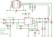
Regarding the voltage out, i have changed the gain to 400 to give an output of 1v (you said it will be 0.8). I may do a dual 5V suuplly at the end.
I have changed the high pass at the output to 10Hz.
I have added the 5*P3 resistors at the input even though i don't understand what they do.
How can i set the low pass frequency at 20KHz?
What is the SQR??
Thank you very much
Attachments
Excuse but i don't know much about opamps.
I had a look on a book and made some assumptions.
correct me if i'm wrong.
Both filters on input and output should be high pass and for a required frequency of 50Hz I should set them to 1 fifth (10Hz) in order the 3db point to be approximatelly at 50HZ.
The low pass frequency will be the highest frequency in the signal times the gain.
Am i near at all?
That will not help. The LM4562 cannot give out more voltage with a single 5 V rail. If you change to dual 5 V rails you will get the 2 V with the gain of 80.bluetech said:Regarding the voltage out, i have changed the gain to 400 to give an output of 1v (you said it will be 0.8).
They are the R in the RC filter. You need them to form a frequency dependent voltage divider with the input capacitors. Same formula as before gives you a high-pass filter with 10 Hz now.bluetech said:I have added the 5*P3 resistors at the input even though i don't understand what they do.
To form a low-pass you need the opposite of the high-pass, i. e. a resistor in series followed by a capacitor to ground. Formula as above, only now it is a low-pass with the same corner frequency.bluetech said:How can i set the low pass frequency at 20KHz?
Square root.bluetech said:What is the SQR??
The - 3 dB point is at 10 Hz. 5 times higher is the - 0,1 dB point, where you can assume that the signal passes unhindered.bluetech said:Both filters on input and output should be high pass and for a required frequency of 50Hz I should set them to 1 fifth (10Hz) in order the 3db point to be approximatelly at 50HZ.
The same situation as with the high-pass, only reversed. If you want to have an unhindered 20 kHz signal, aim for a low-pass with a - 3 dB point above 100 kHz.bluetech said:The low pass frequency will be the highest frequency in the signal times the gain.
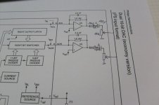
First, the TDA1543 is a current output DAC. This is one reason why paralleling many TDA 1543s is the norm for most DACs.
You might want to message Peter Daniel, he's got extensive experience with this DAC, and has one of the only offerings where a single 1543 is used with passive I/V and is able to provide reasonable output voltage into loads above 20-22K, IIRC. You could do a lot worse, so check with him first.
You'd be better served by using two LM4562, one for I/V conversion and the other for amplification and buffering.
Or redo the passive I/V and use non-inverting configuration for the opamp, without a volume pot in the middle, so you can avoid presenting a low impedance to the DAC output. I'm not sure you'll need a gain of 80x, once you get the I/V sorted out a gain of 5 or 6 should be enough.
Are yuo sure that the TDA1543 is a current output?
I've seen designs that they don't have opamps at the output, only filters.
Thank you
I've seen designs that they don't have opamps at the output, only filters.
Thank you
current output from DAC
Yes, and the R of the RC filter passes the output current and develops the voltage required to drive the next stage.
Yes, and the R of the RC filter passes the output current and develops the voltage required to drive the next stage.
Opamp is not the only way to do I/V, as Andrew says. A simple resistor across the output will convert the current to voltage, and you can use a transformer, tubes, or even a transistor to convert output current to voltage. In the case of a simple resistor I/V, the value of the resistor determines the output voltage and impedance. Usually for a useful voltage level the output impedance is quite high, about 2K or so. This usually means the next stage needs to have a high impedance as well, which makes the implementation tricky.
It's all very confusing to me.
Can I be cheeky and ask for someone with more experience than me to draw a very simple schematic that includes all the nessesary stages (I/V conversion, filtering, buffering) and maybe a volume pot (not completely nessesary).
Thank you.
Can I be cheeky and ask for someone with more experience than me to draw a very simple schematic that includes all the nessesary stages (I/V conversion, filtering, buffering) and maybe a volume pot (not completely nessesary).
Thank you.
I could easily change the DAC as long as the new is DAC low pin and I2S.
I'm not interested in extrmelly high quality or accuracy, something simple.
I'm not interested in extrmelly high quality or accuracy, something simple.
If all you want to do is drive a power amp from the TDA1543, a single 1K resistor at the output will result in 2.5V (p-p) output voltage. (2.5x1000 = 2500mV)
This is enough to drive most amps, as long as they have a input impedance of about 20K or more.
Your current schematic already has this resistor, and deriving the output from the Vout pin should do.
Performance can be a little better if you drop the resistor to half the value, the voltage also drops as a consequence but current output DACs behave better into lower loads. Most amps will have a gain of at least 26dB, so even with 1.2Vp-p you can drive most speakers to normal listening levels (20Vp-p at amp output, which is roughly 50 watts into 8 ohms).
- Status
- Not open for further replies.
- Home
- Amplifiers
- Chip Amps
- Line out using LM4562