As I understand it generally one likes an amp to have a frequency response comfortably beyond the normal audio band to limit phase shift within the audio range. However I wonder if for low to medium powered tube amps where the OPTs are often limited in their ability to pass large undistorted signals in the bottom one or one and a half octaves (below 30 or 40hz) whether it might be more sensible to roll off the response of the input and/or VAS stage to limit the low frequencies to the output stage.
My thought is that any audible phase shift effects would be less objectionable than an over driven OPT. It would also avoid wasting output tube dissipation on frequencies that won't get through to the speaker anyway.
Is that reasonable?
My thought is that any audible phase shift effects would be less objectionable than an over driven OPT. It would also avoid wasting output tube dissipation on frequencies that won't get through to the speaker anyway.
Is that reasonable?
It's perfectly reasonable and it can also reduce the intermodulation of your loudspeakers, but then again, when you have a fixed filter somewhere, it will also phase shift and slightly attenuate the bass of recordings that have little or no content below 30 Hz anyway.
You can have the best of both worlds by making it switchable: keep the high-pass switched off by default, and when you play church organ music or a warped record, just try what sounds best.
If you add it to a feedback amplifier, keep it outside the feedback loop.
That is, it is fine if you can modify the feedback network to give a roll-off below 30 Hz, but don't put a 30 Hz high-pass in the forward path of a feedback amplifier, as that will only result in the feedback trying to correct for the roll-off.
Don´t overthink about low frequency phase shift, we are not sensible to absolute phase.
On the other side, feeding an OT/speaker frequencies below what it can handle will definitely be nasty/audible so better apply a gentle rolloff before audio program reaches it.
On the other side, feeding an OT/speaker frequencies below what it can handle will definitely be nasty/audible so better apply a gentle rolloff before audio program reaches it.
In a related question, as OPT output drops due ro insufficient inductance or core saturation does the phase shift or are those effects phase neutral?
At low frequencies the primary inductance (or magnetising inductance) of the OT has a low impedance and starts to draw significant current from the output tube(s). However, this is in parallel with the speaker load (reflected through the OT). The effect is that voltage delivered to the speaker load is reduced, but not phase shifted.
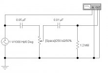
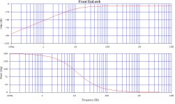
A first approximation would be something like this where C3 and C4 are used to limit low frequency response. Initially the slope is second order but the cathode bypass cap shelves so the ultimate slope is not that great. I think an argument could be made that it could be worth the trouble to implement a higher order filter.

By decreasing the coupling cap to the driver also (making C4 and C1 .027uf) we get -3dB at 40Hz and -10dB at 17Hz which may be adequate. anything further would seem to beg for a separate active filter stage.
By decreasing the coupling cap to the driver also (making C4 and C1 .027uf) we get -3dB at 40Hz and -10dB at 17Hz which may be adequate. anything further would seem to beg for a separate active filter stage.
Last edited:
In a related question, as OPT output drops due to insufficient inductance or core saturation does the phase shift or are those effects phase neutral?
That also causes phase shifts.
@MarcelvdG is correct - my earlier post (#6) was wrong. 😱
The lagging current into the magnetising inductance causes a lagging voltage drop across the internal resistance of the output stage, resulting in a phase lagged voltage to the speaker.
The lagging current into the magnetising inductance causes a lagging voltage drop across the internal resistance of the output stage, resulting in a phase lagged voltage to the speaker.
For Inductors, Voltage Leads Current.
For Capacitors, Current Leads Voltage.
How the output tube sees this is:
At low frequencies, the output transformer's Voltage Leads the Current.
At high frequencies, the output transformer's Current Leads the Voltage.
That means the voltage to the speaker is Leading for low frequencies; and the voltage to the speaker is Lagging for high frequencies.
If someone has to see this on a graph, I might be able to hunt up a screen plot from a Rohde & Schwarz Vector Network Analyzer, and post it here.
One place where it's generally good to put in a high pass filter is at the input of an amp that includes a negative feedback loop and has low frequency roll-offs inside that feedback loop.
Let's say you've got a two-stage amp (voltage amp/driver stage and output tube), with the two stages AC-coupled (with an RC high-pass filter in between the two stages), into an OPT.
If you leave the input DC-coupled (no input HPF) then the voltage amp will accept signals all the way down to DC, and attempt to amplify any it sees at its grid. Its output signal hits an RC-filter that has a roll-off of let's say -3dB at 10Hz. Finally, let's say the OPT rolls off the bass -3dB at 10Hz as well.
Let's say we take the feedback signal off the OPT secondary and apply it to the input tube cathode. The low frequencies have been rolled off twice, once by the interstage RC-coupling network and again by the OPT. The feedback signal to the input tube 'sees' this difference between the output and the (DC-coupled) input, and the input tube attempts to boost low frequencies to make up for their being missing from the output signal. But then as soon as the signal leaves the input stage, that boost is attenuated again by the interstage RC-coupling network, and then again by the OPT on its way to the output. The output signal is now missing that boost (again), the feedback signal sends that signal back to the input, and the input stage attempts to put those 'missing' low frequencies back by boosting them all over again. It can never quite catch up, but it keeps trying. Headroom is lost by the first stage applying so much gain to low frequencies which are promptly rolled off again.
Now if we put a high-pass filter at the input of the amp, rolling off -3dB at 10Hz, and you increase the value of the interstage coupling cap so that it rolls off at a much lower frequency (let's say -3dB at 1Hz), now the input stage doesn't 'see' those lowest frequencies at its input, there's no roll-off introduced by the interstage RC network, so they aren't 'missing' at the output any more. The only roll-off is the OPT. (If the input HPF doesn't allow the OPT to see frequencies much lower than it can handle, then the feedback error signal won't include those very low frequencies either.) The feedback signal can now more effectively apply itself to extending the bandwidth of the OPT and reducing distortion in the amplifying stages, rather than getting bogged down trying to apply an overly large bass boost to put back what was missing at the output from the DC-coupled input signal getting rolled off so drastically.
I hope I explained that well enough. Tough to put into words when you don't know the full depth of how something works in physical/scientific terms.
--
Rongon is absolute correct about bandwidth limiting setups that employ a GNFB loop. Failure to block infrasonic noise is asking for O/P trafo core saturation to occur.
In order to get substantial reduction of record warp noise, use a simple 1 pole (6 dB./octave) RC filter set in the 16 to 18 Hz. range. Things remain HIFI and whatever phase shifts that occur in the audible range are "undectectable" by the human ear. The ear is not sensitive to spatial cues in the deep bass region. That fact is why single subwoofers work. Also, in order to limit cutter excursion in the vertical plane, LPs are mastered with the deep bass summed to mono. Nobody notices that during listening.
In order to get substantial reduction of record warp noise, use a simple 1 pole (6 dB./octave) RC filter set in the 16 to 18 Hz. range. Things remain HIFI and whatever phase shifts that occur in the audible range are "undectectable" by the human ear. The ear is not sensitive to spatial cues in the deep bass region. That fact is why single subwoofers work. Also, in order to limit cutter excursion in the vertical plane, LPs are mastered with the deep bass summed to mono. Nobody notices that during listening.
That -1 dB single pole filter at 16 to 18 Hz will be - 3dB at 8 to 9 Hz. At the typical warp frequency of 3 Hz, it will be even further attenuated. That is a good idea for record playback. Some later RIAA magnetic phono preamps do deploy the modified RIAA curve that cuts off the super low frequencies, for just that reason.
For Inductors, Voltage Leads Current.
For Capacitors, Current Leads Voltage.
True, but we are interested in the contribution to phase shift in the signal (i.e. phase difference between the AC voltage produced by the output tube(s) and the AC voltage at the speaker terminals), caused by insufficient magnetising inductance.
The magnetising current of the OT (into its magnetising inductance) is different from the current transformed to its output.
But once again, I have to apologise for a mistake in my earlier post (#9) . The voltage at the speaker is phase-leading the source (tube) voltage. 😱🙁
Note to self: Think first, type later! 🙂
Last edited:
- Status
- Not open for further replies.
- Home
- Amplifiers
- Tubes / Valves
- limiting low freq on purpose