I want to make a light AC mains phase indicator like as screwdriver with the light indicator phase?
TIA
Felipe
TIA
Felipe
I want an indicator light that lits when the AC mains phase is connected to the right side of the power transformer phase.
I want to make a light AC mains phase indicator like as screwdriver with the light indicator phase?
Like this one?
Amazon.com: Prime Products 12-4058 AC Power Line Monitor: Automotive
More or less rayma, only need that a light lits when is in phase and of course if possible DIY to learn a little.
Only needs like a screwdriver that lits when is the phase, the same with a LED in the front panel of equipment.
An externally hosted image should be here but it was not working when we last tested it.
More or less rayma, only need that a light lits when is in phase and of course if possible DIY to learn a little.
Morris Products 59040 Screwdriver Probe Voltage Tester 80-250 Volts AC/DC - KTOOL
https://www.ebay.com/i/192740323390?chn=ps
I have the screwdriver, I want something to put inside the equipment and a LED that lits when the device is in phase (live circuit). I want to check the phase (live circuit) is going to the right side of the live/phase transformer?
Last edited:
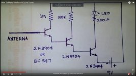
Thanks rayma I will use like the attached schematic.
Perhaps with clamp diodes from the input base to the rails?
Vbe reverse limit is usually fairly low, around 6V or so.
Merlin i am using for correct mains phase indicator
3 elements in series from Ground (Schuko pin) to Negative
in order:
Ground line - R=27K cca (8x220K/2W in parallel) - Anode (Diode=1N4007) Katode - Anode LED Katode - Negative line.
.
IF LED is on light, then it is OUT of phase and should inverse the power cable konector at the wall plug. IF the led is not on then it is right connected.
.
BUT that is not all You should control the power transformer connections.
With that screwdriver tool You already have. IF the mains transformer primary is right connected, then the screwdriver lamp should not light AT the core of the transformer. For that You should unmount transformer from chases if it is EI core. IF it is toroid, You have to lean that it is good marking of wires, because You cant reach the core...
.
With EI or other Classic mains transformer Live has to go on the first layer to the core, first turn has to be on Live. Last output turn is on the last layer from core, and it is goint to Negative line. IF the transformer have some shields or screen blind layers they going to Ground.
In most tof tha cases by visual inspection, at EI transformers You could determine right connection. 🙂
cheers and take care this is the high voltage!
.
You will be amased how many these computer style cables are oposite connected L/N
I check out 9-10 and it was 4 of them with swapped L/N lines. Ground (schuko) was good. Every earlier or "vintage" cable was properly connected...
Thanks Zoran, yes I know the problem about phase of transformers (if I remember well Mark Johnson did a very good jig to know wich one is the phase), what voltage for LED 2V or more, what's cca = carbon composite?
Last edited:
You'd use resistors in series for mains, not parallel, much safer (and many resistors have voltage ratings insufficient for mains).Ground line - R=27K cca (8x220K/2W in parallel) - Anode (Diode=1N4007) Katode - Anode LED Katode - Negative line.
Anyway a capacitive dropper is much less power hungry to light an LED.
have a look at this thread, you might find it interesting:
Kind of useless, but fun: a stray currents harvester
Kind of useless, but fun: a stray currents harvester
You could put an LED with high value resistor in series between phase and earth.
Don't run too many milliamps into the LED or your ELCB might drop out.
Don't run too many milliamps into the LED or your ELCB might drop out.
You could put an LED with high value resistor in series between phase and earth.
Don't run too many milliamps into the LED or your ELCB might drop out.
What's ELCB?
- Status
- Not open for further replies.
- Home
- Design & Build
- Construction Tips
- Light AC mains phase indicator