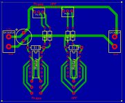
Hi, I'm creating a small board to support some relays and LEDs in a microphone preamp. I am new at electronics, and at board design, so please bear with me.
I am attaching a file of the board, simplified (some circuitry not essential to this question deleted).
My question is, if I have a 15v input, can I use the power across 4 boards like this, using connectors between the boards (shown)...I have a single power rail, and a single ground, going across. I'm wondering when relays/LEDs engage, if the voltage or current will drop.
My understanding is, voltage will remain constant since the individual components will be connected in parallel with the main + and - rails. This would mean the current would be divided amongst all the boards.
I added a capacitor across the power rails at input to smooth out any power drops when the relays/LEDs are engaged. But will this compensate for lost current due to the topology of the board?
Is there a problem with this design; have I missed something fundamental here? I don't want the LEDs to get dimmer as I turn on more and more switches, and I don't want the relays to fail to engage when more and more switches are turned on, due to a lower current. This design would work fine for 1 board, but what about for 4 boards connected together using the Unimate connectors shown, each to each other? Or do I need to get a new power +15v power supply for each board directly from the power supply itself?
Thank-you for answering such a simple question.
Mike

Not knowing the type of relay you are using (coil current) no answer can be given. However it is likely it is a 1000 Ohm (or higher impedance coil) and should not matter. You could allways widen the DC rail traces to reduce the trace resistance.
To the pcb design: Do not put part identifiers under the part but next to it. And I believe that "Phase" should say "Polarity Inverted" (one of my little rants, so ignore it). E
To the pcb design: Do not put part identifiers under the part but next to it. And I believe that "Phase" should say "Polarity Inverted" (one of my little rants, so ignore it). E
Thank-you a million!
You are right; coil current is 1028R and coil current is 11.7ma.
I'll see what I can do about widening the traces.
🙂
You are right; coil current is 1028R and coil current is 11.7ma.
I'll see what I can do about widening the traces.
🙂
Download this toolkit, it will give you voltage drop, current capacity and loads of other PCB related stuff, its indispensible when doing PCB design.
PCB Via Current | PCB Trace Width | Differential Pair Calculator | PCB Impedance
Under the input cap you jave an acute angle, this could become an 'acid trap' during etching, I'd angle it to give a perendicular join.
PCB Via Current | PCB Trace Width | Differential Pair Calculator | PCB Impedance
Under the input cap you jave an acute angle, this could become an 'acid trap' during etching, I'd angle it to give a perendicular join.
- Status
- Not open for further replies.