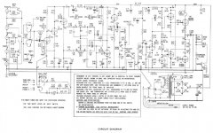
Hi i'm looking to restore a Leak Stereo 30 plus. It has a couple of bad caps in it. So i will just go for replacing the lot. Attached is the wiring diagram
can any of these values be usefully changed to higher values and what would be suggested. I'm thinking mainly of c2 c3 c4 and c6.
Also c34R is a 1000µf electrolytic carrying the audio signal I guess its high to improve signal transmission could this be replaced with a lower value film cap.
any more advice of what i can do would be appreciated
Thanks
Tom
Attachments
Sometimes you have to be a bit careful with changing cap values as LF instability can creep in, but here you could usefully increase some cap values.
With Early transistor amps the manufacturers frequently used the absolutely minimum values they could get away with as cost was an issue.
C34r (or 34l) definitly does not want to be substituted with a lower value as you will lose all bass. This component if anything could go rather higher, at least 2200uF or even up to 4700uF.
The bootstrap cap C32 could well go up to 220uf.
Regards
Henry
thanks for the reply
what would be a good value for C6 with it being the ps smoothing cap i guess it can go quite high? what would a good value for C2,3,4 be? i guess something around the same value?
what would be a good value for C6 with it being the ps smoothing cap i guess it can go quite high? what would a good value for C2,3,4 be? i guess something around the same value?
I've got the copy, the ST120. C34 and C6 are 3300. It will go subsonic, reproducing the thuds of me walking across the floor away from the record player, so I suppose c34 is fine. C6 at 3300 is fine too, it will produce way more than 60 watt/channel until things begin to heat up. If you do increase C6, you might put a NTCR in the transformer input to reduce the surge at turn on. a GE CL-40 or CL-50 maybe. I don't know how tough your transformer is.
C2 & C3, well, the analog C11 on the sT120 is 500 and I put in a 470 when I changed the cap. Sounds fine. Not much current draw on these.
I don't know about the low value film cap on C34. Maybe if you don't like bass. I've auditioned my ST120 with the djoffe bias mod to generate 40 ma idle current on the O.T.'s at all times, and it sounds exactly the same as my capless (in the sound path) CS800s at 1 watt. I use top octave piano as an IM distortion check, against my console Steinway as calibrator. That is on speakers with the 2nd harmonic distortion 30 db down @ 1 W and 3rd harmonic 40 db down.
Putting a back to back 5000 uf electrolytic cap in series with the output of the CS800s was definitely sub-standard. I believe as e-caps go through zero the chemical events make the response non-linear. But with C34 biased at 1/2 rail voltage all the time, there are no such chemical events.
As a final non-related tip, I found the tendency of the ST120 to run away thermally is much reduced by putting PC power supply fans on the O.T. heatsinks. I run it 12 hours a day most of the time now, at 1 W. I don't know what the leak heatsinks look like, but the non-finned ST120 heatsinks were good for about 3 1/2 hours of 10 watts out. On the new watt limit, I've got NTE181 transistors on one side and NTE60 on the other side. These are maybe the equivalent of the MJ15003 as they have a SOA rating. A bit faster than the 2N3055, also. I put 10 pf across the be junction to slow them down a little per dynakit's recomendation for the "TIP" mod.
Last edited:
Ok, C2/3/4 could be 1000Uf.
I would up C22 from 2.5UF to 10uF.
I have often found that C24 can leak a bit putting a bit of DC onto the volume pot (does it crackle?). The value is fine but not available in modern values so a 47uF is a good sub.
Regards
Henry
I would up C22 from 2.5UF to 10uF.
I have often found that C24 can leak a bit putting a bit of DC onto the volume pot (does it crackle?). The value is fine but not available in modern values so a 47uF is a good sub.
Regards
Henry
Oops, forgot C6. The only possible problem here is can the diodes stand the extra charge current. Most likely yes but you could fit higher rated diodes (3A or more-remember that diode peak ratings are rather higher than average current).
Then you could go up to 10,000uF, the transformer will be perfectly Ok.
Then you could go up to 10,000uF, the transformer will be perfectly Ok.
hi
The Diodes fitted are BYX36 150 so Vrrm= 150v, Ifsm=30A, If(av)=1A, Vf Max. at if=1.1V, If 1A, Ir max at Vrrm=1µA
I was thinking of changing the diodes at some stage i guess this would work STPS3150RL - STMICROELECTRONICS - SCHOTTKY RECTIFIER 3A | Farnell United Kingdom.
Thanks
Tom
The Diodes fitted are BYX36 150 so Vrrm= 150v, Ifsm=30A, If(av)=1A, Vf Max. at if=1.1V, If 1A, Ir max at Vrrm=1µA
I was thinking of changing the diodes at some stage i guess this would work STPS3150RL - STMICROELECTRONICS - SCHOTTKY RECTIFIER 3A | Farnell United Kingdom.
Thanks
Tom
would these diodes work VS-31DQ10 as i have four lying around
http://www.vishay.com/docs/93321/31dq09.pdf
http://www.vishay.com/docs/93321/31dq09.pdf
I wonder at the rocket science parts being used here in a stone age amplifier. Surely it would be more authentic and almost
certainly no worse in sound quality, using standard silicon rectifiers and keeping to modest increases in replacement cap. sizes.
Those are 2n3055s, not MJL3281s in a SOTA amplifier and the preamp may not be a device you really want to listen to too closely anyway.
certainly no worse in sound quality, using standard silicon rectifiers and keeping to modest increases in replacement cap. sizes.
Those are 2n3055s, not MJL3281s in a SOTA amplifier and the preamp may not be a device you really want to listen to too closely anyway.
Ian, you're quite right, but the OP did ask, and you could agree that 1000uF is rather inadequate given modern speakers which commonly have Z minima 4R or less.
Is it worth restoring this amp and just replacing the existing caps with the same value or as near as i can get except the speaker coupling cap that could be increased to around 2200µf and the PSU cap That could go to 3300µF
Hi Tom.
Agreed that using the Shottky diodes is rather guilding the lily, but as you have them anyway then you might as well.
2200uF is really a minimum value for the speaker coupler, and as such will work fine, but as you are at it, it might as well be 3300 or 4700.
There is no downside to increasing the PSU cap (but I'm not suggesting doing anything nuts like 22000uF) as it is a bit small so going to 4700,6800 or even 10mF won't harm.
Do the other caps as suggested and it will be fine.
There's nothing wrong with the preamp section and when all done it'll be every bit as good as a Naim (right, now the flack will really start). I'd get strung up for saying that on the Pale Crimson Aquatic food source.
Hi thanks for the replay and advice toprepairman.
I guess you have one of these or have had a lot of experience with them? I got this amp because it was cheep after a quick listen I thought that after a bit of work and refresh it would sound quite good. As it is it's lacks detail in the mid range and the treble has slight distortion at higher frequencies. Having said that I did compare it to another more modern well regarded amp i have and to me it was not that far behind. i have had all the pots out to inspect and clean them the only one that needs replacing is the volume pot.
I guess you have one of these or have had a lot of experience with them? I got this amp because it was cheep after a quick listen I thought that after a bit of work and refresh it would sound quite good. As it is it's lacks detail in the mid range and the treble has slight distortion at higher frequencies. Having said that I did compare it to another more modern well regarded amp i have and to me it was not that far behind. i have had all the pots out to inspect and clean them the only one that needs replacing is the volume pot.
Somebody on solid state forum did a simulation of a leak delta 70, and found upgrading the output transistors really helped the distortion. Started with 2n3772, then 2n3055, then TIP3055. Each has a higher ft spec. The reviews of my Dynakit ST120 (Leak power amp copy) say it was the worst sounding amp ever, but after I got it running I wondered what they were talking about. My OT's were toast so I didn't have an option of going original, but after I put the NTE60 OT's in (maybe white box MJ15003's) it sounded fine. I lucked out on the NTE60's that is just what the store had in 1985 a decade before the internet gave us choice. I've got an unmodified ST70 tube amp, this ST120 (leak copy I think) actually sounds better. The leak 30 is the same geometry, so I would say 3300 output cap for some bass response, and modern higher ft OT's with slew rate limiter cap on b-e leads , it could sound great. No, it won't be 0.002% HD (harmonic distortion). But the speakers aren't either, what is the point? I can hear the 1% specified HD of the tube ST70 on my speakers, but the ST120 and the extremely modern CS800s sound the same at 1 Watt, so the speaker is the limiting factor in mine as in most home setups.
As far as the the sound of other transistors, the one channel has original input transistor and driver transistors (RCA 5 digit TO5) the blown up channel has NTE249 input transistor and NTE49 & 50 driver transistors. The two channels sound exactly the same to me. So ft on the 1970 age driver transistors isn't limiting by my experiment. The biggest source of noise I had were the replacement input 5 uf tantalum caps I installed in 85. I had a popcorn noise for years, until I replaced the tantalum input caps with Aerovox gold 50 v CPO ceramic caps 2 years ago. Yeah, yeah everybody hates ceramics. Popcorn noise gone, I'm sticking with ceramic input caps. Signal <500 mv, cap rating 50v, how non-linear are they? Not very, my ears & speakers tell me.
As far as the the sound of other transistors, the one channel has original input transistor and driver transistors (RCA 5 digit TO5) the blown up channel has NTE249 input transistor and NTE49 & 50 driver transistors. The two channels sound exactly the same to me. So ft on the 1970 age driver transistors isn't limiting by my experiment. The biggest source of noise I had were the replacement input 5 uf tantalum caps I installed in 85. I had a popcorn noise for years, until I replaced the tantalum input caps with Aerovox gold 50 v CPO ceramic caps 2 years ago. Yeah, yeah everybody hates ceramics. Popcorn noise gone, I'm sticking with ceramic input caps. Signal <500 mv, cap rating 50v, how non-linear are they? Not very, my ears & speakers tell me.
Last edited:
Hi Jo.
Know what you mean about the general opinion of ceramics, but as they are only being used as DC isolation and in a highish impedance situation ther shouldn't be any problem at all.
Know what you mean about the general opinion of ceramics, but as they are only being used as DC isolation and in a highish impedance situation ther shouldn't be any problem at all.
- Status
- Not open for further replies.
- Home
- Amplifiers
- Solid State
- leak stereo 30 plus caps