Hello all.
There has been a lot of talk about redesigning both the Leach amp and Leach super amp to fit flat pack transistors in the output section of the amp. I have started this thread to find out if there is enough interest in the DIY community to make this a project.
I feel the need emphasize that this will be a NON PROFIT project (As most other projects here at diyaudio.com) I have had some experiences earlier where I was accused of profiteering from a project I got involved with here. I’m sure the outcome of the project has proven that delta-audio is for our (Jan and I) personal fun of DIY and nothing else. Jan Dupont and I share an interest for making small projects in our spare time, and I humbly offer to make the PCB layout for this project, should there be enough interested.
Now let’s get this project going. Please give your input to the following:
1)Overall component choice (I prefer standard non exotic parts)
2)Layout of the PCB
3)What should be included on the PCB other than the amp components
4)Technology (Double sided, single sided, Surface mount devises etc.)
5)Target price for the boards (to find out how many we need to order)
Keep the ideas coming 😎
\Jens
In case anyone has somehow missed this fact, Jens is a very skilled designer and an eminently honest individual. And since he already has experience in designing Leach amp boards, I am sure that this project will be very successful.
Hi Jens,
I have participated in the Mox Group buy and was very satisfied with your layout.
I support the idea of using non exotic part because I can hardly justify the cost increase over the regular parts. When my ears and my wallet get into a fight, my wallet or wife almost always win...
I have a terrible problem soldering surface mount components so through hole would be best for me.
As for the technology, I'd suggest that the simpler the board, the lower the cost and the lower the cost, the most chances it'll get attention. So single or double sided being often very close in price, I would suggest double sided if the layout can be made smaller this way.
In terms of design I don't really know the Leach Amp or the Leach Super Amp, but by the names, I'd say I'm more likely to be interested by the Super Amp 😉
As for the flat pack transistors, would the MJL4281A (NPN) and MJL4302A (PNP) be useable? (I have a bunch of those left over).
If so, I'd be in for 2 or 5 boards depending on the price. Speaking of which, I think a price between $15US and $30US would be acceptable.
Hope this helps!
Sébastien
EDIT: I second tiroth on that!
1)Overall component choice (I prefer standard non exotic parts)
Non exotic sounds good to me.
2)Layout of the PCB
I would prefer if the PCB' didn't get too much larger than the originals. I know they have to become larger to accommodate the flatpacks but I would prefer if they didn't need huge heatsinks to accommodate them.
3)What should be included on the PCB other than the amp components.
I would like to see the flatpacks included but I rather have the PSU separate to keep the size down.
4)Technology (Double sided, single sided, Surface mount devises etc.)
For me, single sided with no surface mounts. Those little suckers are tough to solder. with single sided, it would be easier for someone to make their own boards if they choose.
5)Target price for the boards (to find out how many we need to order)
I have no idea on this. I am interested in buying some though.
I want to thanks you Jens for taking this on. I will be keeping a close eye on this thread.
Blessings, Terry
Considering how much time and effort Jan and you are investing in a pcb design i'd think you'd have a poor return even if the design was made on a profit basis, Jens.
I'd say any profit interested pcb company is more than welcome to offer high quality PCB's for building Krell's , Leach amplifiers, and the like.
1 Standard, please
2 single channel pcb, with a flexible layout that allows varying
parts size.
3 besides front end and power stage enough space for small PS
caps(electrolytics and several foil types)
I am hoping for enough space to mount wide flatpacks(mt200)
with an option for type of high power source and emitter R's.
4 Double-sided, and regular parts( smd is no diy fun), but i go
with the crowd
i desire 2 at the rate for the number you have made.
Thanks for offering your time, Jens
I loved the pcb work on Delta-Audio
1) Standard
2) I tihk seperate driver/power boards would be nice to allow more flexible mounting options. The flatpaks can take up a lot of room. If seperate, a standard connector scheme would be good, like .1" spaced pins, so a variety of connectors could be used.
3) As little as possible. I am all for a seperate power board.
4) I agree with still4given on single to make it easier to self-make the boards, but 2-sided would likely make them much smaller. Torn on this.
5) Free (ha ha). I guess up to $30USD (?).
Again, Jens is great. He puts a lot of time, effort, and expertise into his work, and expects nothing in return (other than fun, I suppose).
Hi acenovelty,
Nice pictures, what are you points?
Should we not bother with making a new layout in your opinion?
\Jens
Nice pictures, what are you points?
Should we not bother with making a new layout in your opinion?
\Jens
The idea of many is to make it better.
I can easilly make original Leach boards, but i am most certainly not going to.
The pcb is the basis of an amplifier, and should be up to date.
Given the work and money involved a pcb with a professional layout and quality is the proper basis.
Leach did his layout for his students, and made it such that a pcb could be easilly made.
Maybe some may find building amplifiers in amateur diy quality sufficient, i believe most here try doing it better than the pro's.
I can do a better single sided layout of the Leach with a modern pcb designing program in 2 hours.
My pc can do it in Eagle, Ultiboard2001, Orcad, or a bunch of other programs( thank you, FTP's).
I'd alter the layout, certainly would not handwire the output devices, add some extra space for larger or additional components, change the TO3's for flatpacks, make the entire layout 1-dimensional, etc, etc , etc.
If others prefer such a layout too, and Jens likes to do us a favor, i gratefully ask Jens for 2 boards, and spend my diy time building the beasts.
Speaking only for myself, a layout like the original Leach is a waste of time. I invest a lot of effort, i want the best.
Hi Jens,
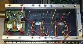
i think all will agree that your prototype board looks professional, the Leach board looks like it has been designed with rolls of tape.
I used to do that in the old days when i did not have the cash for a pc and design software.
The power stage board looks great, though i was hoping for a bit more space between output devices to place MT200 Sanken's or Toshiba's.
If a bigger number of diy members desire your layout and boards like the prototype, i go with the majority and use TO247's.
My preference would be a layout like your prototype, but with both stages on 1 board.
The dimensioning of the boards is to my liking, they are narrow enough to make great single-channel amplifiers, 19' types do not make nice monaural's.
I have a thing for symmetrical layouts, both for the looks as for technical reasoning.
Again, this is a democratic thing, i go with the flow.
If there is sufficient interest for you to make your effort worthwhile, and some like flatcable to build scry-scrapers, i can live with that.
Hi,
People seem to conclude that flat packs take a lot of heatsink space. I do not necessarily agree. One way that I find very compact is to have all the output devices in a single line on one edge of the board and place the board at 90 degrees from the heatsink using metal angles. This way you use only the minimal space on the heatsink. It does make the board slightly longer but it can be slimmer.
This is somewhat different of Jen's extended version... But you can stack many boards vertically or horizontally on the same heatsink.
Would it be possible for the Leach amp to be done that way?
Thanks,
Sébastien
One transistor is 20 mm wide... this results in a least 4 * 20 * 2 = 160 mm edge space + what is needed for drivers and emitter resistors... This does not leave any room for the MT-200 type transistor...
I guess it's one way of going, though I prefer to place the output transistors similar to my prototype design for better cooling (No L bracket)
I don't really care what format the boards are going to have...I'll get my heatsinks when the design is final.
What does everybody else like for layout?
\Jens
Points?
Prof. Leach has published a well documented amp that is extremely easy to build. Most likely thousands have been built in many configurations including the changes I have made and posted here.
I encourage all to participate in making a new layout. Make it "better" if you can.
Even jacco vermeulen says "I can do a better single sided layout of the Leach with a modern pcb designing program in 2 hours.", so this should be quite easy to implement.
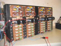
Otherwise, the pics are for illustration purposes to those who have not seen the real thing.
Prosit
Prof. Leach has published a well documented amp that is extremely easy to build. Most likely thousands have been built in many configurations including the changes I have made and posted here.
I encourage all to participate in making a new layout. Make it "better" if you can.
Even jacco vermeulen says "I can do a better single sided layout of the Leach with a modern pcb designing program in 2 hours.", so this should be quite easy to implement.
Otherwise, the pics are for illustration purposes to those who have not seen the real thing.
Prosit
Solution with " standing " output devices is not good for big output power, 'cos in this case are " line of otput " too long ( and rail lines also ) and both must be relatively narrow. Better is Jens's solution ( and the best is my 😉 ).
Standing devices could be solved with a powerline bar soldered on the pcb.
A downside with limited width pcb's that have output devices mounted on both sides is the difficult access when mounting the outputs on the heatsink.
I built AVM's M1 mosfet amplifier from Gunther Mania's article series in the German Stereoplay magazine in the first 8 months in 1988.
I designed the pcb layout for a width of 4' between both heatsinks.
With big heatsinks to do 50 watts in class A i had a really hard time getting the output devices mounted well to the heatsinks.
At a later stage i added two outputs per channel and mounted them non-isolated on an L-bracket, the bracket to the heatsink isolated with a layer of silicone sheet, worked a lot better.
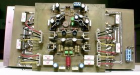
Acenovelty :
take a good look at the pcb of the amp on the second picture you posted and tell me what you see !
A downside with limited width pcb's that have output devices mounted on both sides is the difficult access when mounting the outputs on the heatsink.
I built AVM's M1 mosfet amplifier from Gunther Mania's article series in the German Stereoplay magazine in the first 8 months in 1988.
I designed the pcb layout for a width of 4' between both heatsinks.
With big heatsinks to do 50 watts in class A i had a really hard time getting the output devices mounted well to the heatsinks.
At a later stage i added two outputs per channel and mounted them non-isolated on an L-bracket, the bracket to the heatsink isolated with a layer of silicone sheet, worked a lot better.
Acenovelty :
take a good look at the pcb of the amp on the second picture you posted and tell me what you see !
- Status
- Not open for further replies.
- Home
- Amplifiers
- Solid State
- Leach Super Amp Pcb Re-Design (LSAPRD)