This amp is in protection mode all outputs test fine..
Heres what i get on the 494
Pin 1: 0.04
Pin 2: 4.99
Pin 3: 4.74
Pin 4: 0
Pin 5: 1.49
Pin 6: 3.46
Pin 7: 0
Pin 8: 13.91
Pin 9: 0
Pin 10: 0
Pin 11: 13.91
Pin 12: 13.16
Pin 13: 4.99
Pin 14: 4.99
Pin 15: 4.99
Pin 16:11.16
Any suggestions on what to look at?
Heres what i get on the 494
Pin 1: 0.04
Pin 2: 4.99
Pin 3: 4.74
Pin 4: 0
Pin 5: 1.49
Pin 6: 3.46
Pin 7: 0
Pin 8: 13.91
Pin 9: 0
Pin 10: 0
Pin 11: 13.91
Pin 12: 13.16
Pin 13: 4.99
Pin 14: 4.99
Pin 15: 4.99
Pin 16:11.16
Any suggestions on what to look at?
Post the DC voltage on all 8 pins of the IC next to the TL594.
IC#
Pin 1:
Pin 2:
Pin 3:
Pin 4:
Pin 5:
Pin 6:
Pin 7:
Pin 8:
IC#
Pin 1:
Pin 2:
Pin 3:
Pin 4:
Pin 5:
Pin 6:
Pin 7:
Pin 8:
IC# JRC 2904D
Pin 1: 0
Pin 2: 12.31
Pin 3: 6.52
Pin 4: 0
Pin 5: 11.48
Pin 6: 4.99
Pin 7: 11.56
Pin 8: 13.15
Pin 1: 0
Pin 2: 12.31
Pin 3: 6.52
Pin 4: 0
Pin 5: 11.48
Pin 6: 4.99
Pin 7: 11.56
Pin 8: 13.15
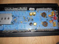
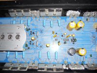
lol, just repaired the exact amp a couple months ago. anyways, looks like this one has been repaired before, especially obvious with the one mismatched rail cap (the black one.) the 2 on the other side look to be bad, or going south. is that leakage below them? also, look at the one above r203. i would also check the to-220 drivers between the top outputs in the pic. it looks like one might be touching the screw, or the other could be contacting beyond the pad. all i can see.
I found the drivers for the power supply fets to be defective..
The amp uses IRFZ44V's for the fets with 100 ohm gate resistors..
The amp is using A1015 and C1815 as the drivers..
Are there any good subs for the drivers?
The amp uses IRFZ44V's for the fets with 100 ohm gate resistors..
The amp is using A1015 and C1815 as the drivers..
Are there any good subs for the drivers?
Are you sure that they're defective?
It's rare for the drivers to fail if the FETs are not defective.
It's rare for the drivers to fail if the FETs are not defective.
Positive they are defective amp draws excessive current when trying to power up so i removed the drivers and they are shorted from legs 2 to 3
The BD139 and BD140 are good generic replacements.
How did this happen? Was the amp drawing excessive current previously when you were measuring the voltage on the various ICs?
Did the power supply FETs fail also?
How did this happen? Was the amp drawing excessive current previously when you were measuring the voltage on the various ICs?
Did the power supply FETs fail also?
Amp waesnt drawing excessive current when i was measuring the voltages ..
I found a solder bridge on the cap that is different from the rest of them and it was shutting the amp down and it wasent drawing excessive current now that i clened the solder bridge off the amp trys to power up but draws excessive current..
None of the fets test bad.. I know it seems wierd that none are bad and it didnt draw excessive current off the get go..
well, i would imagine that the lack of switching would not allow it to power up the rail voltage. have you double-checked the output section for failures?
Ok i removed all of the outputs in this amp...
Amp powers up now and idles fine ...
The Tl494 voltages dont look right to me but maybe im wrong heres what i have on the 494
Pin 1:4.99
Pin 2:4.99
Pin 3:3.55
Pin 4:0.08
Pin 5:1.49
Pin 6:3.47
Pin 7:0
Pin 8:12.80
Pin 9:0.72
Pin 10:0.72
Pin 11:12.76
Pin 12:13.12
Pin 13:4.99
Pin 14:4.99
Pin 15:4.99
Pin 16:0
Do theese look correct or is something wrong ?
I don't see anything that appears to be a problem. It appears that the power supply is up and running and is producing its target rail voltage.
Ok if i install the outputs in the left channel amp will power up and produce audio on the left channel..
If i leave the left channel outputs in and install the right channels outputs the amp will power on for about 10 secs then the power light just fades out and amp shuts off..
Any ideas?
If i leave the left channel outputs in and install the right channels outputs the amp will power on for about 10 secs then the power light just fades out and amp shuts off..
Any ideas?
Will either channel produce audio when the LED is on?
Does the amp draw excessive current during the 10 seconds that it's on?
Is there any significant DC voltage across the right channel speaker terminals at any time after you power up the amp?
Does the amp draw excessive current during the 10 seconds that it's on?
Is there any significant DC voltage across the right channel speaker terminals at any time after you power up the amp?
Ok i found that problem i found a shorted transistor ..
Next problem is 1 channel has louder audio then the other i cleaned the switches and moved all switches and knos thru rntire range still same thing any ideas?
Next problem is 1 channel has louder audio then the other i cleaned the switches and moved all switches and knos thru rntire range still same thing any ideas?
You would need to drive identical signals into both channels and find the point where the signal varies from one channel to the other.
How much of a difference is there?
How much of a difference is there?
- Status
- Not open for further replies.
- Home
- General Interest
- Car Audio
- Lanzar MXA282